
In my never-ending cloning/upscaling efforts I had a need to venture beyond the straight body tube. I needed a lightweight material that could be carved and that could be glued together to create variable thickness and length. I remembered a foam insulation product called Foamular. It’s a high-density foamboard product that can be cut, sawed, hot wire cut, sanded, and is very lightwieght. This foamboard product available at most major home improvement and lumber stores in thickness of 2” to 5”, and either in 2’ x 8’ or 4’ x 8’ sheets. The following is about my first rocketry project made with Foamular.
Create the Foam Core
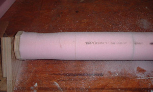
First in this project I ripped on the tablesaw two pieces of Foamular that measured 2” thick x 4” wide and 4’ feet long and glued these together with a thin layer of DAP Panel and Foamboard Adhesive. This glue comes in a caulking tube and is available at most hardware stores. This gave me a core that measured 4” thick, 4” wide, and 4 feet long. I allowed the core to dry overnight and then trimmed the corners off at 45 degrees on the tablesaw to match a 4” circle to save work. This gave me an eight sided octagon shaped core to work with
CAUTION: The Foamular is solvent sensitive and will melt and give off toxic fumes if solvent glues, adhesives, epoxies, and fillers are used! Use only solvent free glues, epoxies, and fillers on this foam. Test small pieces first to see how the foam reacts before trying any other adhesives or fillers on larger areas.
Motor / Recovery Sections
Next I decided to make the motor mount and recovery sections before carving so I could take advantage of the flat surfaces left on the core. Before cutting any sections make alignment reference marks across each section to be cut. I cut two 8” sections off of the rear end of the rocket with the tablesaw marking each section to its mate. The rear 8” section became the motor mount section; the forward 8” section became the recovery/ parachute section. I next drilled out the two 8” sections to fit a BT-60 body tube using a 1 5/8” hole saw. This hole was very snug so I sanded the inside to fit using a 1/2” dowel and 150-grit sandpaper. Next I cut two 12”sections of BT-60 to be glued into the two drilled sections. Cover one end of each of the 12” BT-60 tube with masking tape and push it through pre-glued hole (DAP adhesive), past the tape and set aside to dry. After the glue has dried cut the BT-60 off flush with the foam. Glue the forward recovery section back onto the upper core. Next lightly tack glue the recovery and motor mount sections together for the carving process. These sections will be separated after the carving and sanding process is complete.
Homemade Lathe
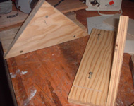
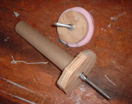
Next we need some homemade lathe brackets and a front and rear spindle mounts to turn our Foamular project on. The size of your spindles and brackets will be determined by the size of your project. Nothing fancy is needed. I used some 3/4” plywood to make the spindle support brackets and the spindles. I fastened two ¼ inch x 4 inch bolts to the center of the spindles to act as the turning axles.
I next centered and attached a BT-60 coupler tube (paper towel tube) to the rear spindle to help center the engine mount on the spindle. Next I glue the spindles to the core and let glue dry completely before mounting spindles and core on the lathe brackets. I blocked and shimmed a half inch drill in alignment with the rear spindle bolt to power the homemade lathe.
Turning the Core
The best speed to turn the foam core for carving is between 150-350 RPM. Turning any faster and the core will begin to wobble out of round and eventually break off. It is best to first round the core completely for balance with a wood rasp. No pressure with the wood rasp is needed, just a gentle touch as the foam carves quickly. For deeper cuts the foam can be rough cut to shape with a hobby backsaw and then shaped more with the wood rasp.
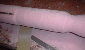
After the rough shape is attained begin sanding with 50-80-grit sandpaper to smooth out the surface. Use a respirator to protect yourself from the fine dust that is created during any sanding. The sanding process can be graduated to 150, then 220, then 320, and then 400 to attain a smooth surface. Also sanding sponges, small files, and emery boards can be used for shaping and finer detailing. It is best to wait to carve any nose cone and boat tail sections until last, as carving near the spindle mounts may weaken the mounts.
Use a hobby backsaw to remove the carved rocket from its mounts and finish the front and rear by with a little hand sanding. Also pits and scratches can be filled with lightweight and easily sandable hobby filler while the rocket is still in its mount. It is also wise to plan on putting a protective finish on the rocket while it is still on the mounts to avoid any accidental damage during handling. Once your rocket is removed from its mounts it can be easily damaged without this coating.
Ejection Baffle and Shock Cord Mounts
I decided to go with an ejection baffle system with an eyebolt shock cord mount because of the size to this rocket. This section is about 6” long and will also be used for the coupler tube, ejection baffle, and shock cord mount on the motor section. Using the Bt-60 coupler tube I tape dammed one end and centered the eye bolt in it. I next poured epoxy into the coupler tube at least 1/4” thick to cover the eyebolt nut. When the epoxy is dry drill several 1/4” holes for the ejection charge to provide separation.
A second eye bolt attachment will be needed for the recovery section. This section was made from a 1” piece of coupler tube and tape dammed with the eyescrew hole to the INSIDE of the coupler tube. Pour epoxy in the same way as above being sure to surround the nut with epoxy and let dry. I next tied a 3/8” braided elastic shock cord to this eyebolt and glued it in the forward end of the recovery section using a long couple tube to push it into the pre-glued section.
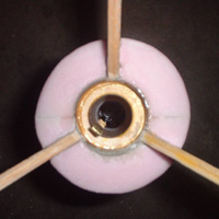
Fin Attachment and Motor Mount
I decided to go with a 24mm motor mount tube which I had on hand and custom made my own centering rings from 1/4” balsa plywood. I next used a hobby backsaw to notch out fin slots in the foam down to the BT-60 tube and glued them in with foamboard adhesive.
Protective Coating
I decided that my rocket needed a protective epoxy coating so I decided to use Devcon 60 minute epoxy and skip any fiberglass cloth to save weight. The epoxy coating without the fiberglass cloth proved to be unsatisfactory for strength. I have recently discovered 3/4-oz. fiberglass cloth, slikspan cloth, tag board, vaccum bagging, carbon fiber matte, and intent to cover the rocket when time and finances allow.
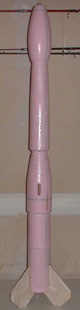
Rocket Named: “IT”
I have decided to name this rocket the “IT”. The finished is 47 inches long and 3 3/4 inches in diameter at IT’S widest point. The IT has been swing tested and nose weight has been added to make it flight stable. An test flight was attempted, however while I was hooking up the wire leads a at a local park I was told by the park caretaker that rockets were not allowed in Mason County Parks so I had to leave.
Submitted by: James Pierson