
General Description
The launch controller shown is designed to handle 6 launch pads. Because the panel uses an adjustable rotary switch, the design can easily be expanded to accommodate 12 pads. The controller has a removable main arming switch, a secondary safety switch, and a launch button. It uses red LED’s to indicate pad chosen and green LED’s to show igniter continuity. Igniter continuity is continuously displayed with igniter standby current of about 13 ma. Arming is indicated with a high intensity blinking red LED and an audio alarm.
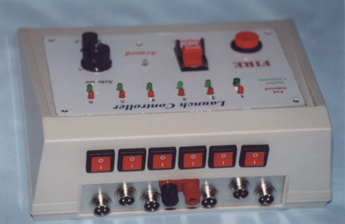
Simultaneous launches are possible using the red switches on the back of the control panel. Using the front panel to fire any pad which has a red drag race switch turned on will simultaneously fire all others which have their red switch turned on. The panel’s selection LED’s will indicate which pads are chosen for a “drag race”. The system is designed to minimize the probability of an inadvertent launch caused by a short in the wiring leading to the control panel. Power to the relay is supplied from the controller panel.
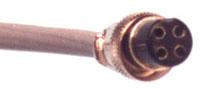
Microphone connectors were used between the control panel and the remote relay pads so that control wiring can be easily replaced.
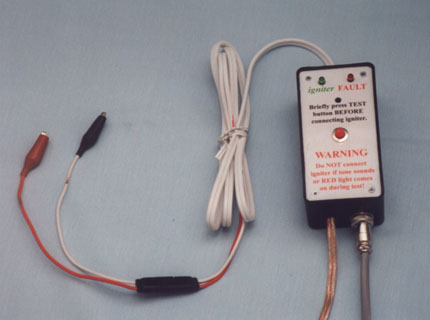
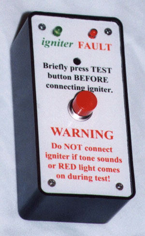
- There is a safety test button at each pad on each relay box. It should be pressed briefly before connecting the igniters. This will cause an alarm to sound at that relay box and a red alarm LED to display if there exists the dangerous condition of continuous power at the igniter connectors (i.e. the relay contacts are welded).
- Green LED’s (at both the pad and at the launch controller) continually indicate the status of igniter continuity.
If you are new to electronics, please enlist the assistance of someone with experience before beginning this project.
The panel face should be completed with all switches added before wiring is begun. LED’s should be wired before being glued in place with SuperGlue.
A simultaneous launch with 6 rockets requires that part of the control wires inside the control panel carry the current to operate all 6 relays. The wire in this portion of the circuit must be sized accordingly. This includes all wire in the circuit before it splits off for the individual relays. Other hookup wire in the control panel can be 20-22 ga.
Radio Shack part numbers are referenced. However; to keep costs within reason, you should consider ordering compatible parts (with the exception of the slope panel box, project boxes, and the controller’s blinking LED and low current piezo). It is important to use the same type of LED for any LED’s which are wired in parallel (i.e. igniter continuity in controller and relay box at pad). Mixing LED’s with different voltage/current specs may cause, one LED to be bright while the other is too dim to view.
IMPORTANT DESIGN CHANGE: Initially, this project had a weakness in common with many other controllers. LED’s (even high current ones) are very difficult to see in direct sunlight if they are made with colored plastic. Recessing the LED’s, surrounding them with black tubing, placing a hood over them, and/or darkening the surrounding faceplate helps little. REPLACING THEM WITH CLEAR LED’s COMPLETELY SOLVES THE PROBLEM. USE ONLY CLEAR LED’s IN THIS PROJECT.
Despite the higher current specs of the clear LED’s, CURRENT LIMITING RESISTORS KEEP CURRENT LOW AT THE IGNITER (and at the rotary switch during simultaneous launches). The resistors also limit the voltage drop across the igniter during continuity testing. To prevent LED dimming when multiple pads are selected, one resistor is now used for each LED. (You may wish to substitute a large LED for the Blinking one. Its blinking can be inhibited by direct sunlight.’ %}
| Qty | Description |
|---|---|
| 1 | package of 9” x 12” self-adhesive laminating strips–Avery |
| 1 | package of high resolution inkjet paper |
| 1 | sloped panel box (for launch controller)–Radio Shack |
| 6 | project enclosures (boxes) 5” x 2 1/2” x 2”–Radio Shack 270-1803 |
| 1 | electrical junction box for power cable spider near a centrally located launch pad |
| 6 | large ScotchLocks |
| 6 | 12VDC (9.6VDC pull-in, 75ma) DPDT 15 amp plug-in relay–Radio Shack 275-218 |
| 6 | 10 amp relay socket–Radio Shack 275-220A |
| 12 | clear red LED–Radio Shack 276-307 |
| 1 | clear blinking red LED (12ma)–Radio Shack 263-308 |
| 12 | clear green LED–Radio Shack 276-304 |
| 6 | 5.6k 1/2 watt resistor–Radio Shack 271-1125 (package contains 5 so you need 2 packages) |
| 12 | 4.7k 1/2 watt resistor–Radio (package contains 5 so you need 3 packages) |
| 1 | 1k 1/2 watt resistor |
| 1 | fire button |
| 1 | main safety switch |
| 1 | momentary pushbutton switch SPST normally open–adio Shack 275-609A (used for secondary safety pushbutton) |
| 6 | momentary pushbutton switch DPST (used for test button on pad box) |
| 6 | rocker switch DPDT–Radio Shack (used for simultaneous launch switches) |
| 1 | adjustable 12 position, 3 pole rotary switch (Allied Electronics C4D0312N-A) Only 6 positions required for 6 pads |
| 1 | 1” knob for standard 1/4” shafts–Radio Shack 274-416A (4 to a package but only need 1) |
| 12 | 4 pin male panel-mount microphone connector–Radio Shack 274-002A |
| 12 | 4 pin female microphone connector–Radio Shack 274-001A |
| 7 | 12VDC (3.0-16VDC) piezo mini buzzer (7ma)–Radio Shack 273-074A Don’t let the loud annoying sound of this buzzer fool you. It is not overpowering outdoors and provides unmistakable indication of arming. You may wish to substitute a different buzzer for main control panel if you plan to announce the launches on a P.A. system but a finger on the hole during countdown is a better choice. (Extremely low current is not a requirement for the control panel buzzer and armed LED provided that the total current for the two is significantly below the pull-in threshold for the relay.) |
| 1 | 4 ft length of 1/8” heat shrink tubing |
| 1 | 500 ft roll of 4 conductor stranded 20ga phone wire |
| 1 | 130 ft 16ga speaker wire (for connecting battery to relay boxes) (Home Depot) |
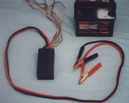
| 1 | 12 ft automobile battery jumper cable (8 ga or 10 ga is all that is necessary) (K-Mart) |
| 1 | 12v lawn tractor battery |
| 9 | Alligator clips (You’ll need the extras for a multi-engine igniter whip) |
| 8 | quick connectors (for the igniter whips) (K-Mart) |
misc.: superglue, DuPont spray adhesive, Exacto knife, wire, power connectors, batteries, launch rods, launch pads, deflectors
Clicking the images below will allow you to download printing templates. The larger download may take about 3 minutes or more.
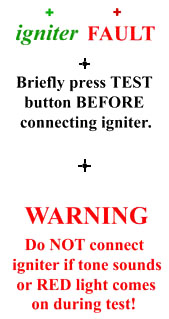
Full size for printing (194Kb, print 4 up horizontal)
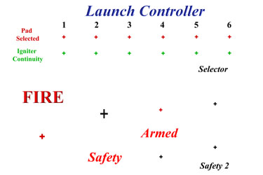
Full size for printing (441 Kb)
- Print templates using a color inkjet. (Print several extras.’ %}
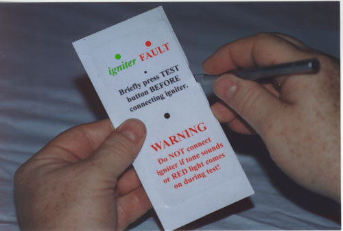
- Temporarily tape a template to the control panel and use a center punch to mark the drill holes and insure that their location does not wander during drilling. Drill round holes, then cut out rectangular switch hole with a Dremel tool. Mounting the LED’s will be much easier if their holes are just a little snug.
- Use scotch tape to secure the corners of a self-adhesive laminating sheet (adhesive up) to a flat surface. (If you have one, you will find that a 7 ½” airframe coupler works better than a flat surface.’ %}
- Next you will carefully adhere the printed panel face template (face down) to the to the laminating sheet. This is tricky, so, align and adhere one edge and bend the sheet of paper as if rolling it on. Slowly and carefully slide a finger back and forth over the paper as it meets the laminating sheet. After the entire sheet is laminated, slide your finger back and forth across the entire surface while pressing hard.
- Cut the templates apart and place them face down on some newsprint. When you spray them with adhesive, they will try to curl. You can prevent this with a very light layer of adhesive on the newsprint. Spray a light coat onto the back of the paper template. Don’t put spray adhesive too thick on back of paper. Spray adhesive on the top of the panel cover. Remember to let it dry for about 30 sec so that solvent doesn’t cause paper to wrinkle or peel from the plastic while it is drying.
- Allow short (10-20 minutes) drying period after adhered.
- Trim excess with an Exacto knife.
(Holding the panel horizontally and slicing mainly downward will yield the best results.’ %}
Trim holes similarly.
(Practice. If you don’t succeed the first time, remove the adhesive with rubbing alcohol or dissolve it with turpentine, clean the surface, and try again.’ %}
 Cut X in screw holes rather than trimming them.
 - You may want to sand the surface of the clear blinking red LED so that it appears frosted. This increases the viewing area for this clear focused LED. An unsanded LED is much brighter but is not visible from an angle.
- Use a reasonable amount of SuperGlue to mount LED’s. (Excess glue can darken the panel face around the hole.’ %} Patiently allow to dry. Study the one pad control schematic first. It is included to make the multipad version easier to understand. The wiring of the pad relay boxes is identical in both versions.
Make the hookup wires at least three inches longer than necessary. For safety reasons, heat shrink tubing should be used on all connections inside the panel, connectors, and relay boxes. I used hot glue afterward to further secure the wiring on and around the LED’s. I chose to use a spider for power distribution because locally, we launch mostly large scale and smaller models. Any pads located a significant distance from the others would benefit from a separate battery (especially if high power clusters are used.’ %} The gold colored speaker wire supplies power to each pad. Lately, I’ve seen more people using power cord plugged into receptacles and rolled up for storage. This has many advantages including ease of disconnection, availability of replacement without repair, cost, etc.. Caution should be used if this method is used because the plugs could mistakenly be plugged into 110v by launch setup personnel or by children at home.
LAUNCH SITE - Pad 6 below is actually 120’ away from the control. Also, moving launch control away from the publicly accessible area makes it much easier to maintain control of the launch. Lengths were cut to allow the following layout. To prevent tripping, all control wire fed to a central point near the spider box first then fanned out. (Green is control wire. Grey is 12 volt.’ %}
COMMENTS FROM THE DESIGNER: Hopefully, this project will help growing clubs fill the void between single pad controllers and the equipment which is used for large numbers of pads. Criticism and suggestions for improving the design are welcome.
Submitted by: Charles Barnett