
Background
This write up describes a simple relay based launch controller. This launcher has successfully fired 4 clustered Estes igniters and single Copperheads, and should easily handle any e-matches. The continuity test current has been tested at 38 mA (0.038 Ampere) with the LED & resistor combination described used. If you prefer to use a Piezo buzzer, that is easily accomplished by replacing the LED.
This is the classic tinkerer’s project. Most of the parts can come from your junk box. Table 1, is a parts list of equivalent parts that can be found at your local Radio Shack. The Radio Shack part numbers for each are provided. Other sources like TechAm or Digikey) should carry substitutes. The majority of the parts can be low current and are easy to substitute. The thing to remember is the relay and wires from the battery and to the igniter must be of sufficient gauge to keep resistance losses down to a minimum. A relay that can handle 10 A at 12 VDC across the switching contacts is required.
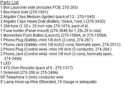
Figure 1, illustrates a crude schematic of the launcher. As you can see there are very few components to this system. The principle of operation of the system is centered around the relay. This provides the means to provide as much current to the igniter as possible. This is done by locating the battery as close to the igniter as possible. The relay allows you to remotely switch the power to the igniter. This circuit takes advantage of both sides of one set of contacts in the relay (the normally open and normally closed). The part number recommended is a double pole double throw type, but a single pole double throw will also work. The entire circuit is protected by a 20 Amp slow blow fuse on the positive side of the circuit. This supply splits to power the hand controller and connects to the normally open terminal contact. Power to the hand controller is interrupted by the safety key (plug). With the plug inserted power goes to the open side of the launch switch and the LED. The LED orientation is important here if you want it to light when you have a good igniter connection. Typically the long end of the LED leads would be hooked to the wire coming from the positive battery connection. The 470 ohm resister prevents too much current from being passed to the igniter and keeps from burning out the LED. The continuity circuit is completed through the top wire back to the launch box to the normally closed contact of the relay and then out to the igniter and back to the negative side of the battery. If you have your igniter hooked up right and the safety plug inserted, the LED will illuminate. There are many LEDs available so a part number for the LED is not provided. Many have built-in resistors, potentially eliminating the need for the 470 ohm addition. Make sure you pick one with a higher voltage rating. Measure the current through the system with the LED alone first, this will help you determine the level of current you would like to allow through your igniter, before you push the launch button. Pete Kerchoff at Pbp has very nice write up on this in his free projects modification of the Estes launcher. He also has a very cool 4 pad launcher there too, as well as a lot of other very interesting projects, check it out.
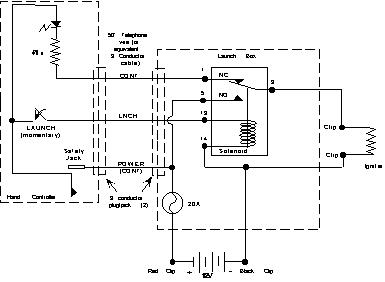
When the launch button is pushed, the coil in the relay is energized and pulls the switch from the NC position to the NO (normally open) position, this completes the circuit for the battery’s positive terminal through the igniter back to the negative terminal. Nothing to impede the progress of electrons to the igniter, except the fuse, clips and wire. This also interrupts the continuity circuit and the LED will go out. As long as the momentary switch is held the contacts will stay closed, if the igniter burns through and breaks the circuit your done. If it doesnt (which can happen) thats where the fuse comes in.
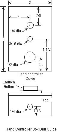
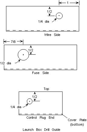
Figure 2 and 3 are drilling guides for the holes that you will drill in the Hand Controller and Launcher Boxes. You may have to modify the location of the parts dependent upon which parts you substituted. A test fit prior to final drilling (measure it twice before cutting it once) is recommended. All dimensions shown are in inches.
Building It
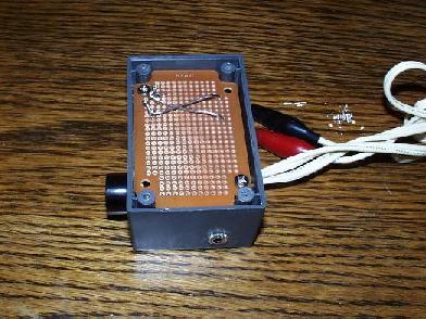
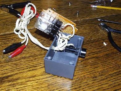
After you have bought/scrounged your parts, lets start with the Launcher box. The hole diameters listed in Part 1 mirror the original design, if you use different parts, make sure the hole sizes are big enough to put the threads through, but small enough for the flange and nut that hold it in place to do their jobs. Drill the three holes in the box that are shown in Figure 3. The control wire jack on the end of the box, and the fuse is located on the side, its placement is important because you want to leave enough room for the relay inside this box. The box recommended comes with a Printed Circuit Board (PCB) included, this board can be used to attach the relay. Connections can then be made to the terminal tabs on the base of the relay connector. Dependent upon the relay you choose, you may solder the relay to the board and solder all your wires to their appropriate spots. The relay recommended will only fit horizontally. Figure 4 shows the PCB mounted under the cover, and Figure 5 shows the mess of wires inside under the PCB. Lamp cord was used for hookups to the batter and ignitors, you may substitute lighter gauge wire for the energizing portion of the wiring. Make sure the to use a heavy gauge for the connections from the battery to the igniter. The battery wires and igniter wires are routed out the same hole on the side of the box. This box left little room for connectors, if you want to use banana jacks for these or terminal hook-ups you may want to use a bigger box. Utilize a large red clip for the positive battery terminal and the black for the negative connection, as the polarity is important for proper operation of the continuity circuit.
You will notice the plug used for the controller wire has three distinct contacts. The following description assumes you are holding the plug by its cover, with the plug pointing up. In the launch and hand controller boxes, the wiring for the Power connection (the one from the fuse in the launch box and the one to the safety key in the hand controller) on the jack should come in contact with the lower most contact of the plug. The launch connection on the jack (the one used to energize the relay) should come in contact with the middle contact of the plug. The continuity connection (the one to the normally closed contact of the relay and from the LED in the hand controller) on the jack should come in contact with the top most contact of the plug.
Alternate #2
If this hook up is insufficient and you don’t like the idea of someone kicking out a connector. There is another option. Radio Shack makes a 4 pin screw on connector (P/N 274-001 plug, $1.99 and P/N 274-002 panel mount jack, $1.79), that is typically used for CB and Ham microphone plugs. You may replace the phono plugs recommended with these plugs. You will only use 3 of the 4 pins for this application. There should be enough room in both boxes to handle the larger hole (1/2 inch) and slightly deeper penetration into the box for the connections.
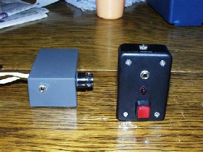
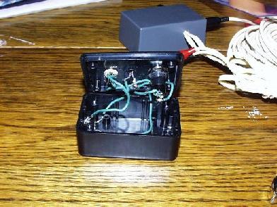
The hand controller (on the right in Figure 6) uses the smaller of the two boxes. Drill four holes in this box as shown in Figure 2 of Part 1. The bottom hole is for the momentary launch button, the center hole is for the LED, the third hole is for the safety key (plug). The control wire plug is located on the end of the box. Figure 7 shows the inner wiring. Use 18 AWG hook-up wire. Leave enough extra wire between the connections since you may have to periodically get inside the box, and you don’t want it to be so tight you wont be able to replace individual parts. Notice the LED and resistor are soldered together. The LED is held in place with CA. Remove the cover of the safety key plug and solder a small fine wire between the two terminals shorting them. You can add a streamer to the plug to make it easier to find in the grass (or snow). Hook up the continuity, launch and power wires on the same terminals of the jack you chose on the launch box.
The control wire from the hand controller to the launch box is a 50 foot section of 4 conductor telephone wire. Since we are only using 3 wires and telephone hook up wire has 4, you can substitute any appropriate 3 conductor wire. Stranded telephone wire will hold up best. Make sure you hook up the appropriately colored wire to the same terminal on each plug.
Testing
Before you commit to a real launch, test the unit.
1st test: First go over your wires and connections again, making sure you trace all the paths as per the schematic in Figure 1. Before you hook up a battery, you will find it useful to use a Volt/Ohm meter in the resistance setting to check continuity where it should be and also verify were it shouldn’t be. When you think you have it hooked up right, it is time for the first smoke test.
CAUTION!
12 volts doesn’t seem like a lot of, but if youve ever welded a jumper cable to something under the hood of a car or had a battery blow its top off in your presence you know that it isnt the volts its the amps and the acid in the batteries is extremely dangerous. A lead acid motorcycle or garden tractor battery can make a very large spark if treated improperly, and remember what we are ultimately doing here is shorting the terminals of the battery together! Albeit for a short period of time.
2nd test: Make sure the fuse is NOT installed. Connect the two controller wire plugs in to each box. Do not install the safety key plug. Make sure the small igniter clips are not touching one another. Connect the large red clip to the positive terminal and the large black clip to the negative. No smoke? Did you hear the relay click? Did the LED light? No, good now you can move on to the 3rd test. If you have smoke, you did something very wrong. If you heard the relay click or the LED lit, there is also something very wrong. If you answered yes to any of these questions, disconnect the battery terminals quickly and go back and check your wiring. If you still don’t see anything wrong have someone else take a look. A second set of eyes can usually catch the obvious.
3rd test: Make sure the battery is still disconnected. Insert a 0.5 amp fuse. Make sure the control plugs are still in and make sure your igniter leads are still separated from one another. Connect the battery terminals as in the 2nd test. Take the two igniter leads and touch them momentarily. While they touch the LED should be on. If everything is still ok, you can hook them together, as long as they are shorted the LED will light. If the LED doesnt light, use your Volt/Ohm meter in the Volt position and hook up the test leads to the two igniter leads independently. If you see 0.5 volts or somewhere around there, you hooked the LED up backwards (or you put the red clip on the wrong battery lead). Reverse this and try again. If you see 11 or more volts with the meter and the LED is still does not light when the leads are shorted together, you may have a bum LED and Id replace it. If you see zero volts on your meter across the igniter leads, youve got a broken wire somewhere or your controller cable plugs arent all the way in. Check that you have continuity from the resistor to the normally open contacts of the relay and on to the igniter lead. If your unit passed this test, move on to the 4th test.
4th test: If you passed the 3rd test, you can now see if your launch circuit will connect the battery to the igniter. Make sure the igniter leads are not touching. If you have your Volt/Ohm meter handy you can hook it up to the igniter leads so you can watch the voltage change. Insert the safety key in the jack all the way. The LED will probably not be on, if you have the volt meter on the leads, but you should see 11 to 11.5 volts on the meter after you put the key in. Push the launch button and you should hear the relay click and the voltage should jump up to 12 or more volts (if your battery is fully charged). Release the button, you should hear the relay click again and the voltage should drop down to the 11 to 11.5 again.
5th test: Now comes the real test. Install the 20A fuse now. Go outside for this one (if you don’t, you will be thrown out right after your first success) and make sure there is sufficient room between you and your igniter. If you have an Estes igniter laying around you can try your system on that. Make sure the safety key is out. Connect the clips to the igniter leads. Go back to your hand controller box and put the key in. The LED should light. When you push the launch button, the igniter will flash in a success. If not go back through the previous debugging described above.
Viola!
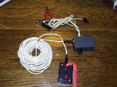
You’ve done it. Barring a major failure of a wire or battery on your way to using it for the first time, the unit should be ready to go. Make sure you have a freshly charged battery for best performance. Figure 8 shows the entire system in its completed form. This unit is compact (it easily fits in the top tray of most launch boxes), simple and packs a pretty good punch. No failures yet (knock on wood).
Why didn’t he do it this way?
Some people will look at this and say why didn’t he.? Well you probably could.
Probably the biggest difference between what is described here and what others have done is the use of modular telephone hook ups. Originally that was the plan planned, but the cost of the modular plugs or an already built cable made it less attractive, Bessel mount jacks can be found in from Digikey (P/N H9062-ND).
You may also substitute a NiCad battery pack for the Lead Acid, just make sure you supply at least 12 Volts to the relay and igniter. Another choice would be the sealed batteries found in R/C modelers boxes.
If you don’t like lugging a battery around separately, you can integrate the entire system into a small toolbox which should leave room to store the hand controller and wire.
Conclusion
If you buy everything brand new from Radio Shack you will spend about $50, without tax and the battery. You may want to scrounge through your junk box for some of the parts to save some money. This class should help anyone put together a launcher that can be assembled in one or two nights of tinkering.
Submitted by: Eric Ohmit
The design for building a rocket launcher contains a problem that under certain circumstances may cause the unexpected ignition of a rocket engine. The problem lies in the use of phono plugs and jacks to connect the hand box to the launch box. When the phono plug slides into or out of the jack on the launch box, the contacts on the plug will momentarily touch more than one contact in the jack which may activate the relay and provide power to the igniter clips.
This can happen regardless of whether the hand side is plugged in, or if the safety key is in place. If the plug is not completely inserted, or inserted slowly, this condition may exist for an extended period of time. Since this launcher design is quite powerful, Estes solar type igniters will fire very quickly, perhaps in the time it takes to insert the plug. Heavier igniters like copperheads are less likely to fire on a momentary activation, but any may fire given an incompletely inserted plug.
In the interest of safety, the launcher should be completely assembled and tested before connecting it to an igniter. A 12 volt automotive light bulb connected to the igniter clips is an easy way to test the launcher, the bulb should be lit only when the key is in place and the launch button is pressed. If the bulb is lit at any other time, then check your system and do not connect to an igniter until the problem is resolved. Another option would be to use some other type of connector such as telephone (RJ11) plugs and jacks, where each contact does not slide against any of the other contacts, or simply hard wire the hand box and the launch box together.
Submitted by: Michael Short