
Success with Copperheads (and all other igniters) at Tripoli Central California
Testing Your Igniter
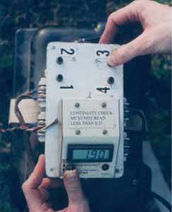
The igniter check at Tripoli Central California is what makes the successful operation of the system possible. Flyers test their igniters with special meters and write the igniter resistance down on their flight cards. These meters will measure any resistance from 0.01 ohm to 19.99 ohms and are accurate to within 0.01 ohm. Their calibration is checked with calibration standard resistors.
Like the igniter testers at NASA, our test leads are Kelvin connected so the reading is not affected by the length of the wires. But unlike NASA, we use the same igniter clips on our testers as we use at the launch pad; so that the test will accurately show whether or not the igniter will work in the launch system. This is of critical importance when using Copperheads, as you’ll see below.
Why We Use Meters
There is another system on the market that uses a simple LED system to indicate a short. The problem is, the resistance of good igniters varies so much between different types and brands, how can you set one particular value of resistance to define the difference between a good igniter and a short? Your choice of igniters is limited with such a system, and clusters read like a short. That’s why I chose to use meters, combined with the intelligence of the human mind, in my system.
Recording the Test Results
Writing down the igniter check reading on the flight card is important. Even if all your igniters are perfect and never misfire, the LCO needs your igniter resistance reading in order to properly interpret the reading on his console when checking the continuity of the ignition circuit to your rocket. Our unique system will tell the LCO if there is a short, a poor connection, clips are dirty or touching each other, or one igniter in a cluster is open or shorted. But it requires the cooperation of the flyers for proper operation.
For proper interpretation of continuity check readings in our system, the igniters must be measured with an accuracy of 0.05 ohm or better. So it is important that the flyers test their igniters with our meters rather than their own ohmmeter or DMM.
The igniter check, obviously, weeds out bad igniters, thereby preventing a lot of misfires. But that’s not all. The igniter check also catches any igniters that, although they may be good, are too low in resistance for our system (such as some Thermalite wire-wraps) and could damage the relay contacts by drawing too many amps. An igniter or cluster of igniters having less than 0.14 ohms resistance should not be used with our system. The continuity reading at the high power pads should not be less than 0.33 ohms.
In addition, if there is a problem with a particular brand of igniter, a pattern will show up in the flight card data, allowing us to recognize the problem and tell our members about it. Even if the problem is that people are using the wrong igniter for their type of motor.
The Continuity Check Function
The continuity check function of the launch control system used by Tripoli Central California is more advanced than any other system (including the Veri-Fire) and operates somewhat differently. Our system’s design was based on actual research and testing of igniters, and refined through operational experience over a period of several years.
The continuity-checking circuit measures the actual total resistance of the firing leads, the igniter clips, and the igniter, with an accuracy of 0.01 ohm. This reading can be displayed at the relay box or at the control console up to 1,000 feet away, with the same accuracy. With this feature, the Launch Control Officer can verify the condition of each igniter, and its connections, before pushing the launch button. This helps to prevent misfires and ensure that all the motors in a cluster will ignite simultaneously.
If a misfire does occur, and the rocket is still on the pad, the LCO can use his control console to immediately check whether the igniter fired. There is no need to guess.
The resistance reading, when interpreted properly, will reveal any of the following problems:
- A broken igniter lead or bridge wire (open circuit).
- A loose connection in the firing circuit.
- High resistance due to dirty or corroded leads or clips, a weak igniter clip spring, a loose screw on the terminal strip, or contamination of igniter leads or clips with skin oils or o-ring grease.
- A short circuit due to igniter clips touching each other or nearby metal hardware, broken insulation, wires pinched by metal hardware, or wires touching within the igniter itself.
This ability to tell what kind of problem a firing circuit has makes fixing it much easier and quicker.
Safe for Flashbulbs and Electric Matches
Our test current is only 10 milliamperes; our system is safe for flashbulbs and electric matches. Our system keeps the igniters shunted at all times except when checking continuity or actually launching the rocket, to protect against accidental ignition from a discharge of static electricity (ESD).
Igniter Check Procedure
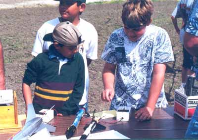
The igniter check so simple, even kids can do it by themselves.
- Step 1: Hook up the alligator clips to the igniter.
- Step 2: Turn the meter on.
- Step 3: Read the numbers on the digital screen.
- Step 4: Compare the reading with the normal reading for a good igniter of the type you are using. If you don’t know what a normal reading is, look up your igniter on the chart.
- Step 5: If your igniter is good, write down the reading on your flight card in the space provided. You’re done! The whole process only takes about 10 to 15 seconds.
High Power vs. Model Rocket Procedure
The igniters of high power (H and larger) motors must be installed at the launch pad or in a designated preparation area. Thus their igniters must be checked before installing them. The igniters of low power motors can be installed before taking the rocket out to the launch pad, thus they can be tested after installation.
Estes igniters should be checked after being installed because they often break or short during installation.
Testing Copperhead Igniters
Our system was specifically designed to successfully fire Copperheads. But you have to follow the proper procedure. Copperheads and their cousins, Tiger Tails, should be tested both before and after installing them in the rocket motor. Before installing them, you should check them at one end, and then the other end. The reading should be about 0.10 ohm lower at the coated end.
Copperheads should be tested again after installing them in the rocket motor because, like Estes igniters, they are easily damaged during installation.
Saving Shorted Copperheads
Some Copperheads that test shorted aren’t really shorted, until you attach the clips; then a short occurs at the clip because one foil was pulled around to the other side at the edge, allowing the clip to contact both foils at the same time.
Some Copperheads may actually be shorted at the uncoated end. In either case, try splitting the uncoated end. (Applying heat to melt the plastic insulation between foils helps. A sharp knife blade makes the process much easier.) Then connect the clips to the split ends, taking care to put the contact disks on the clean side of each foil, not the side with the plastic on it. Then test again.
Boosting the Copperhead
With Copperheads it is very important to attach the right amount of an ignition booster, such as thermalite, pyrogen dip, or one or more slivers of Blue Thunder propellant, to each Copperhead and/or to the surface of the propellant grain next to the Copperhead. This is especially important when clustering, even if you are only clustering F motors.
Never cluster Blackjack motors without using plenty of ignition booster. Try single motors first, to learn how much booster is required for quick and reliable ignition. It’s best to cluster only the same type of propellant; don’t mix Blue Thunder and White Lightning until you know just how much ignition booster it takes to get both kinds to ignite with exactly the same speed.
Cluster Procedures
Unlike other systems, the launch control systems built for Tripoli Central California will tell you whether or not all the igniters in a cluster have continuity. Our systems will also tell you whether or not the clips need cleaning, or there is a short. Here’s how it works.
Checking the Igniters
First, you measure the resistance of your igniters individually using one of the igniter test meters provided at the RSO table. All of the igniters should read approximately the same. If they don’t, this is the time to replace any that read much higher or lower than the others. This helps to ensure that all the igniters will heat up at the same rate, and you don’t have a bad one mixed in with the good ones. You write these readings on your flight card.
A cluster of Estes igniters should be tested again after twisting the wires together, because Estes igniters are very delicate and can break when the wires of igniters in a cluster are twisted together. (To avoid this problem you can use a clip whip.)
If it is a high power rocket, or uses Copperheads or Firestar igniters so that each igniter will be hooked up to its own pair of firing leads, write down the resistance readings of all the igniters individually on the flight card. Otherwise, write down only the resistance of the cluster as a whole. This is the reading the LCO will need to compare with the continuity reading on his console.
Checking the Cluster
After connecting your igniters in parallel, you measure the resistance of the combination. This resistance should be equal to the average resistance of the individual igniter, divided by the number of igniters. For example, if the igniters are 2 ohms each, and you have connected four of them in parallel, then the reading should be about 0.50 ohms. (A reading of 0.67 ohms would tell you one igniter does not have continuity.) For high power motors, this will be done at the launch pad using the removable meter from the relay box. It unplugs, and you can carry it over to your rocket. When you’re done, plug it back in. You may skip this step (though it’s safer not to) and just do the continuity check. If the continuity check indicates a problem, you may want to come back to this step.
Checking Continuity
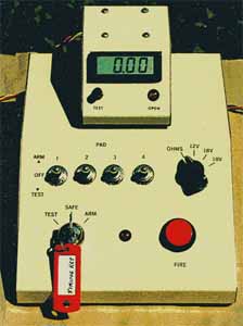
After connecting the clips to the igniters, you check continuity using the meter plugged into the relay box. First make sure the meter is turned on. Then you press your pad button on the relay box, and manipulate the toggle switch on the meter in the proper direction for making the continuity check. When plugged in, this meter reads the igniter resistance, plus the resistance of the clip leads, plus the contact resistance of the clips. Its range is 0.01 to 19.99 ohms.
Normal Continuity Reading
The resistance of the clip leads is approximately 0.17 to 0.20 ohms for the short leads, and in the neighborhood of 0.25 to 0.30 ohms for the long ones (that go to pad 1 or 4).
The contact resistance of the clips is approximately zero to 0.03 ohms or so when the clips are clean.
Thus, if you have a cluster of igniters that reads 0.50 ohms by itself, and you are on Pad 2 or 3 so you have the short clip leads, then you should get a reading of about 0.50 + 0.17 + 0.03 = 0.70 ohms or so when you do your continuity check.
You can also ask the LCO to do the check for you. (An intercom is provided for your convenience.) He will get the same reading from the meter on his console, up to 1000 feet away. He needs your igniter resistance reading to be written on your flight card, in order to interpret the reading he gets on his meter.
It is especially important when launching clusters with this system that whoever does the continuity check knows how to interpret the reading.
Continuity Reading Higher than Normal
A higher reading than normal when launching clusters means one of two things. Either the clips are dirty, or one or more igniters does not have continuity. If one igniter in a cluster of four igniters (each 2 ohms) does not have continuity, then the resistance of the cluster will be 2 divided by 3, = 0.67 ohms. With the resistance of the wires and the clips, you would get a reading of about 0.87 ohms instead of 0.70 ohms. If you got such a reading, you would want to check the clips and the cluster separately to determine which problem you have.
The clips can be checked visually, and also by shorting them together and performing a continuity check. This check reads the resistance of the clip leads, plus the contact resistance of the clips, which was explained above. For example, the short leads should read about 0.17 to 0.20 ohms with the clip leads shorted. IMPORTANT: Always un-short the clips immediately after taking the reading, to make sure nobody ends up pushing the launch button with the clips shorted.
The igniter cluster can be checked by unplugging the meter from the relay box, taking it over to the rocket, and connecting the meter’s test leads to the igniter (making sure the firing leads are disconnected from the igniters first, of course). Making sure the meter is turned on, manipulate the test switch in the proper direction for testing igniters. The reading you get should be equal to the individual igniter resistance divided by the number of igniters that have good continuity.
Continuity Reading Lower than Normal
A lower than normal continuity reading indicates a short circuit. The clips may be touching, or an igniter may have become shorted. This can be checked using the removable meter. It is very important, especially when launching clusters, to trust the system and not try to launch anyway when the system says there is a short.
You can check the clip leads for a short by removing the clips from the igniters, and securing them so you know they aren’t touching. Then do a continuity check. You should get an open-circuit indication.
The igniters can be checked for shorts using the meter from the relay box; unplug it and take it over to the rocket.
Clustering with Copperheads and Firestars
The very idea of clustering Copperheads is heresy to a lot of people in other clubs, and Aerotech says not to do it, but it works here because our system was designed to do it. The design was based on scientific testing of many Copperheads. Up to four Copperheads or Firestar igniters can be clustered at Tripoli Central California launches by borrowing leads from other pads connected to the same relay box. The clip leads have special high-current clips designed for use with Copperheads. Each igniter is connected to its own set of clip leads, and is tested for continuity individually. (It’s important to pay close attention to all the continuity readings, and not go ahead and launch if a reading is wrong. Believe the system, otherwise you run a serious risk of ignition failure in one or more motors.) The LCO then runs the system in drag-race mode to launch the cluster.
When clustering Copperheads or Firestars it is very important to make sure all the clips are nice and clean. You can check them for the proper low resistance as explained above.
Test the individual igniters first, match them for equal resistance, and write down the readings on the flight card. Do not cluster Copperheads that have a resistance less than about 0.7 ohms. Save those for single-motor flights, split the tails and re-test, or throw them away. If you don’t have enough good Copperheads left, that’s no excuse for trying to use bad or mismatched ones anyway; go and get good igniters of some other brand, or scrub the cluster launch.
When clustering, it is especially important to use an ignition booster (in the right amount) as explained above to ensure prompt and reliable ignition of all the motors after their igniters fire.
Modular Redundant Design
Two identical consoles are used in this system. Each console normally controls a different group of launch pads. If a console fails, we simply plug its relay box into the other console temporarily, and keep on launching. There is no need to halt the launch while someone frantically troubleshoots the console and then repairs it–if he can find the parts to do it with, out in the boonies, on a Sunday.
The meters are contained in meter modules, which plug into the consoles and the relay boxes. Any meter module can be plugged in to any console or relay box. Thus, if a meter fails, that meter module can be unplugged in an instant and replaced with any of the other meter modules in the system.
In addition, some of the meter modules double as igniter testers. They can be used as igniter testers where they are, or they can be unplugged and taken over to a rocket to test the igniter after it has been installed. Sometimes an igniter is damaged or shorted during installation, and this system will detect that.
Troubleshooting at the Pad
If any of the fault conditions listed above is indicated, and visual inspection does not reveal the problem, you can unplug the meter module from the relay box. Take it over to the rocket, disconnect the firing leads from the igniter, and re-check the igniter while it is in the rocket. (The very low test current from the meter is safe for all igniters, including electric matches and flashbulbs).
Submitted by: Bob Dahlquist