Dolphin Camera
| ELECTRONICS |
|
Altimeters
Accelerometers Timers Cameras Data Acquisition RF Interference Internal Wiring Dolphin Camera
ELSEWHERE |
 |
BACKGROUND
Let me begin by saying I am no expert when it comes to model rocketry. It is one of those things I did as a kid and have only recently discovered there is way more to rocketry than just the old Estes A through D size rockets and motors, which was basically all we had here in Australia when I was growing up.
After discovering all these wonderful new types of rockets I purchased an Aerotech Mustang to get me back into model rocketry. After having a ball with this rocket and seeing what other people had done with aerial photography, I wondered if it was possible to put a camera in a rocket body only 47mm in diameter. Sure I thought and so I purchased the Aerotech Arreaux, which has a reasonable sized payload bay for such a small rocket (by High Powered rocket standards). What follows is how I managed to squeeze a radio controlled digital camera into it.
Please note that this system was a real trial and error job. There are probably plenty of better ways to assemble some of the parts, use certain glues, cutting methods, etc. The method I'm describing is the way I did it. And one last thing worth mentioning, due to the fact that we live in a crazy world dominated by litigation, I felt I had to include a disclaimer at the end of this document, just in case something untoward happens. That said, let's get busy.
A SLIGHT MODIFICATION TO YOUR ROCKET
Before getting started, I suggest you make sure your payload bay has a nice clean bottom to it. In the Arreaux rocket the upper "Screw Eye" that the shock cord attaches to, sticks into the payload bay. To avoid damage to anything you put in there (especially from a sharp pointed screw), I cut a piece of 2mm ply the exact diameter of the payload tube and slid it in and glued it in place. If you decide to do this, do it first so that you have an accurate size to work to with respect to the length of your payload bay.
THE CAMERA
The first thing I had to do was find a camera not only small enough to fit inside, but one that could be mounted effectively in some sort of cradle, one that would take minimum intervention from me to actually take a shot and a camera that wouldn't cost an arm and a leg. After looking at a number mechanical cameras of various sizes, I stumbled across a fantastic little camera from Dolphin Peripherals in California called the "Dolphin Pocket Digital Camera". This little marvel is so small yet does so much.
I've included the PDF instruction manual from Dolphin that will explain everything you need to know about the camera. But just briefly here are its specifications:
- Sensor Type: Color CIF (352 x 288) CMOS image sensor
- Image Performance for Video Stream:
- 9 fps for CIF (352 x 288)
- 20 fps for QCIF (176 x 144) - Memory & Images: SDRAM 16Mbit (1M x 16): 20 Pictures for CIF, 80 Pictures for QCIF
- Dimension: 125mm x 30mm x 25mm
- Battery: Two AAA 1.5 volt alkaline batteries
- Battery Capacity:
- Continuous: 2 hours
- Stand by: approximately 2 weeks - Lens View Angle: 54 Degrees
- Focus Mode: Fixed
- Focus Length: 5.2mm
- Exposure Control: Automatic
- Auto Shut Off: 30 seconds
- Self Timer Duration: 10 seconds
- Software Support : Microsoft Windows 98(tm),
Microsoft Windows 2000(tm),
Microsoft Windows ME(tm),
Interface Type: USB
The other great thing about this camera is if you hold the button down, it automatically takes its maximum of 80 shots which you can reassemble into a video on your computer with the software supplied with the camera.
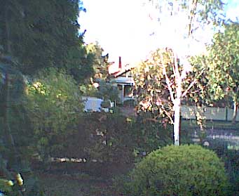
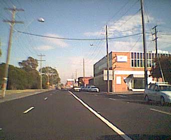
Of course the thing that appeals most to the 47mm rocketeer, is the physical size of the unit, which means it fits very easily into the payload tube of an Aerotech Arreaux rocket. The other great thing is that it only cost me around A$140 which works out to about US$70. Plus being digital, there's no film to worry about and I just have to connect up my laptop to the camera via the USB cable after a flight and I can see the shots it took out in the field. Please be aware that you are buying a cheap digital camera so the picture quality isn't what you get with a $1000 digital camera, but then what do you expect for such a low price - but they're pretty good. The .pdf instruction guide has a few samples in it and here are two of my own, taken with my camera. The first was taken standing still, the second from a moving vehicle.
THE RADIO CONTROL UNIT
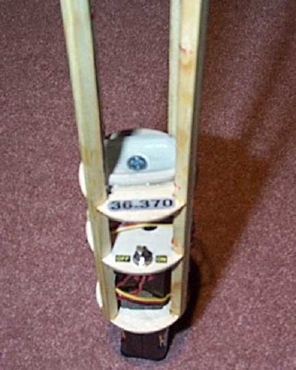
The radio control unit I am using for the ArreauxCam is a pretty basic one. It's a "Hi-Tech" brand FM unit that operates on a frequency of 36.370MHz. As I already had a radio control unit fitted to a model glider, it was simply a case of unplugging the receiver, on/off switch and battery pack from the glider and I was set. However, the next thing to figure out was what to do about a servo. I needed something from Hi-Tec that would work with my existing unit, but was also very small and lightweight. Off to the hobby shop where I came across an incredibly small but powerful sub-micro servo known as the HiTec HS-55. Here are its specifications:
| Model/Type | HS-55 Feather |
| Torque (kg/cm) | 0.6 (4.8v) |
| Speed - 4.8v/6.0v at 60� | 09sec(4.8v) |
| Suggested Application | Micro Planes & Helicopters, Hand launch gliders |
| Bearing | None |
| Size - L x W x H (mm) | 20.9 x 11.4 x 22 |
| Weight (g) | 7.8 |
This gutsy little servo has enough power in it to press the button on the Dolphin camera, with no problems at all.
CRADLE CONSTRUCTION
There were two things I had to work out up front. How to hold the camera in the rocket and how to trigger it to take a shot. What I came up with is a type of 'cradle' that slides inside the payload bay and holds everything needed to take a photo.
The basic design of the cradle is similar to that of a model aircraft frame, so for ease of explanation, I'll use a few model aircraft terms to describe the main parts of it.
The most important terms are 'stringers' and 'formers' and in case you're not familiar with the terms, I'll briefly explain them.
A stringer is a strip of timber placed lengthwise to form the 'ribs' of a frame, ie they run from one end of a fuselage to the other in a model aircraft. Formers are the flat sections that hold the stringers up and in place. I guess they're like bulkheads set various distances apart along the fuselage.
For this cradle, I cut 4 stringers and 4 formers. Although you'll see that there is a fifth former that a buzzer sits on, right on the very top of the cradle. If you're not putting the buzzer in, you'll only have to cut 4.
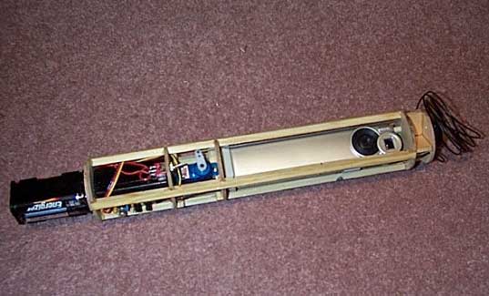
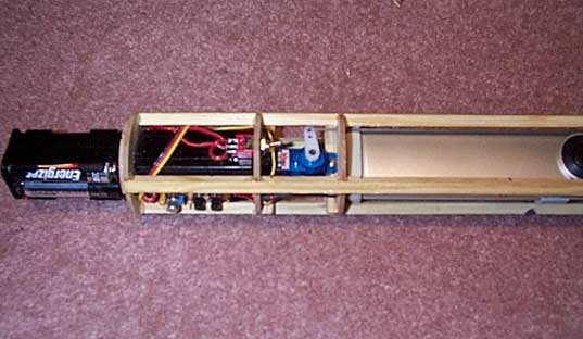
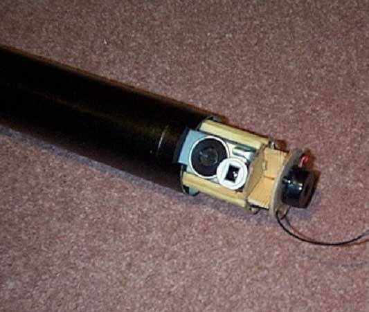
Here's the complete camera unit with the stringers running from left to right and the ply formers running up and down holding them in place.
The formers are cut from 2mm thick plywood, that you'll get from a local
hobby shop and their diameters are as follows:
3 x 44.5mm
1 x 43.5mm
1 x 40.5mm (Optional 5th former)
To make things easy to follow, let's number them from bottom to top and in
this order:
#1 - 44.5mm
#2 - 44.5mm
#3 - 44.5mm
#4 - 43.5mm
#5 - 40.5mm
The stringers are cut from 5mm x 5mm timber which in my case was pine, but just about any variety of model aircraft grade timber will do. The four stringers are 225mm long.
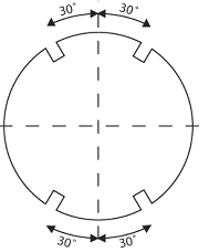
Once you have these cut, you need to put the cradle together. Take formers 1,2,3 and 4 and mark on them four notches, 5mm x 5mm at a 30� spacing left and right of the centre line, top and bottom. I know this sounds strange but if you look at the picture below you'll see what I mean.
This is how your formers should look when cut.
Once you've marked and cut out the notches, test fit your stringers to ensure they fit firmly. Once that's done, glue your stringers into the formers at the points shown on the dimensions photograph below. Note that the measurements are taken from the centre of one former to the next, NOT the inside measurement.
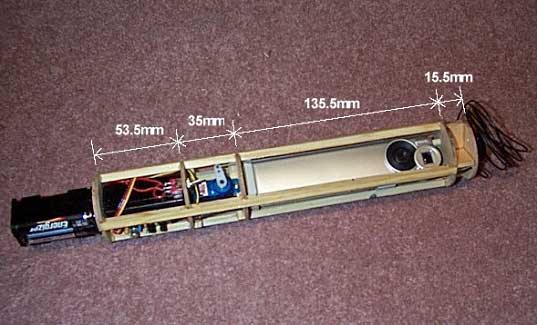
The completed unit with the measurements between each former.
I used an epoxy glue for strength but I guess a Cyanoacrylate Super Glue such as "Flash" would work. The only reason I use epoxy is that I can trust its strength and I loathe using Cyanoacrylate glues as I can never get them to stick. Anyway, that's up to you.
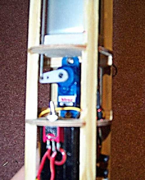
The space between formers 1 and 2 is obviously just big enough to get the receiver in. The space between formers 2 and 3 is just big enough for the servo. And the space between 3 and 4, is just big enough for the camera. The space between 4 and 5 is just big enough for the 'throw' of the rod that runs between the servo and the push-button on the camera. Try to keep the tolerances as tight as you can.
INSTALLING THE HARDWARE
Putting the receiver, servo and camera in is a little fiddly, but the closer the fit the more you'll lessen the chance of movement from the G-forces of flight on the payload.
CAMERA INSTALLATION
Probably the first thing to fit is the camera. To get it to 'clip' into the cradle, I began by taking the plastic desktop holder that you get with the camera and cutting it down so that it was only 7mm high. As the inside bottom of the holder has plastic reinforcing tabs, cut these out so that you have a nice smooth inside base. Next, mix up some epoxy putty and push it into the cut-down base. Then place a piece of plastic food wrap over the base of your camera (to protect it) and push it into the epoxy and make sure it's square and vertical. This will make a nice firm fitting base for your camera to sit in. If you look at the picture below, you'll see the base.
Wait for the epoxy to dry, trim it off flush, sand it, etc. so that it looks neat.
The next thing is to get the camera in just the right spot. Doing this takes a bit of fiddling around but it's not difficult. Here's how.
You get with the camera, a plastic pocket clip, which clips onto the back of the camera. Clip it on and slide the camera into the top of the cradle. Place your bottom holder under it, as this will lift it up a little. Slide the camera to one side of the cradle (call it the back if you like), and see where the pocket clip sits in relation to the stringers. Mark the point where the underside of the pocket clip is lined up with your two back stringers. This will be where your supporting rod goes through, and supports the top of the camera. I used a piece of 3mm steel rod (again from the hobby shop), as it is the right size for the pocket clip to clip onto and not move. Next, cut the pocket clip down so that you only have to lift the camera 2-3mm to unhook it off the rod. Whatever the amount is that you have to lift it, you must allow this much clearance between the top of the camera and former 4, so that you'll be able to get the camera out to change batteries, etc.
Drill your holes through the formers and slide your piece of rod through, glue and cut to fit. Test fit the camera again with its base on.
The next thing to do is attach the camera base to the upper side of former 3. To do this (A 5 minute epoxy is best for this one), spread some glue roughly where the base will sit, slide the camera in and press the base with the camera sitting in it, into the epoxy, then let dry. As you can see in the previous photo, I also included a cut-down screw through the centre of it, just to be sure. Below is a photo of the camera in place.
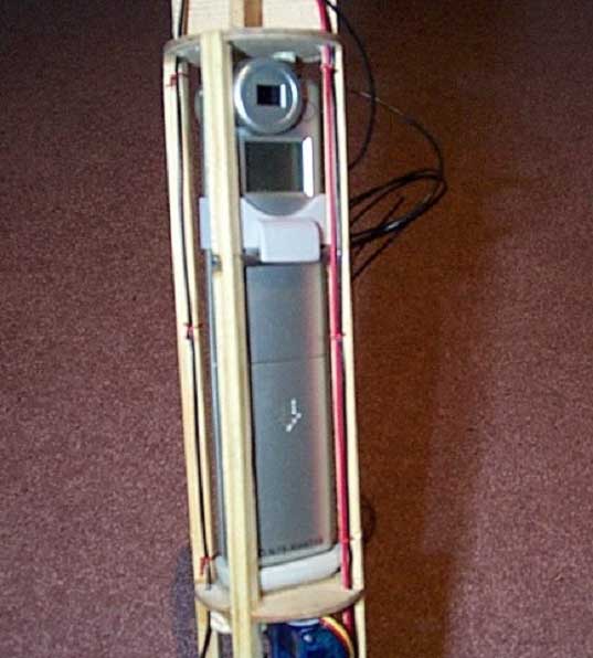
You can see the completed base and rod that the pocket clip actually clips onto to secure the top of the camera.
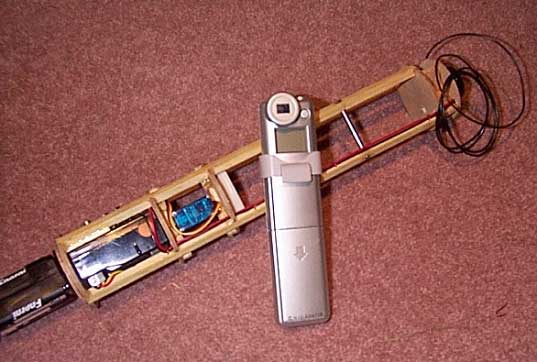
Here's the camera out of the cradle. You can see the rod that it clips onto 3/4 of the way up the cradle, running between 2 stringers.
SERVO INSTALLATION
Now that your camera is in, you can put the servo in. This is quite easy and is just a matter of gluing two 5mm x 5mm timber strips within the cradle and then screwing the servo onto them. One strip goes on the upper side of former 2, the other on the lower side of former 3, up against the two back stringers. Positioning of the servo is takes a bit of adjustment, but basically as long as the control linkage from the servo to the camera button clears the stringers and the camera, that's all that matters. Also don't forget to drill a hole through former 2, to run your servo cable through to the receiver.
Sorry about the blur, but you can see the servo screwed into position.
RECEIVER INSTALLATION
Next you have to fit the receiver. It slides in between formers 1 and 2 and kind of locks itself into the space with all the wires, plugs and switch around it to stop it from moving. You'll also need to drill a hole in former 1 to run the + & - wires from the batteries to the receiver.
You'll also need to drill holes through formers 2,3,4 and 5 to run the antenna wire through. Make sure you attach the antenna wire to the inside of one of the stringers, so that it can't wave about during flight.
Here's the receiver in place. As you can see the on/off switch for the receiver and servo hold it in place.
BATTERY INSTALLATION
You've probably noticed that the battery pack is on the bottom of the cradle and that the batteries aren't your typical AA size normally associated with R/C receivers but AAA batteries. The reason for putting there is that I didn't want to overload the top of the rocket, it was starting to get "top-heavy". Also, the reason for changing to AAA batteries was primarily for weight reduction. I figured that as a flight is so short and the number of shots being taken quite few, the drain by the receiver on the batteries would be minimal. Whatever size you go with, glue the battery holder onto the base of former 1, and thread the wires up through former 1 ready to be connected into the receiver.
The battery holder glued onto the bottom of former 1.
SERVO CONNECTION TO CAMERA BUTTON
This is probably the most difficult part of the whole project - but not too difficult. The first thing to do is take off the battery cover on the camera. Then undo the two screws holding on the back of the camera. Then carefully pry the two halves open. (Yes I know, it's a brand new digital camera and I'm telling you to pull it apart. I was nervous at first but once I'd done it once... no problems). The two halves are held together with tabs that will pop apart. The only hard one is the one at the top which takes a little more effort but will pop open.
Being careful not to touch anything inside, remove the plastic push button at the top of the camera - it just comes out, you'll see it when you open the camera. Then put the camera back together again - snap back the two halves, put in the screws, battery cover - done. The actual switch that is depressed when you take a photo, is soldered onto the PC board inside the camera, so the push button you are taking out is just a piece of plastic that allows you to push the button down.
Using the plastic button as a guide, make up a lump of epoxy putty bigger than the original button, particularly in length. Once this has dried, you need to carve a new button exactly the same width/diameter as the real one but 13mm in length. Constantly check it's size against the hole in the camera's body. When it slides up and down freely but not loosely, it's ready.
You now need to make the rod that links the servo and the button. I used a piece of 1mm wire and bent it to form a right angle on one end to go through the hole in the servo's plastic arm. A small blob of solder was put on the end of this so it wouldn't slip out.
Next work out just where the hole for your new camera button has to go through former 4. This takes a bit of time to get right but it's not difficult - just a few measurements to get the hole in the right place. If you make your hole a little bigger than the button, it gives you room for adjustment , but don't make it too loose.
Next you'll need to drill two holes through formers 3 and 4 for the servo rod to the button. Again it's just a bit of measuring to get them in the right spot and as with the button hole, make them a little larger than the rod to allow for adjustment.
Once your holes are cut, drop the button in to the camera so that it sticks up through the top of former 4. Thread the servo arm onto the rod and slide it down to the bottom. Slide the rod up through formers 3 and 4 and attach the servo arm on to the servo.
By pressing your new button down you'll see that the servo only has to move the button by around 1-2mm when it's sitting on top of the switch inside the camera. So mark on the rod sticking up through former 4, where a right angle bend has to go, then another bend so that the rod will stick into the centre of the new button. The picture below will give you some idea as to what the rod looks like.
A fairly crude drawing of the connecting rod shows it's rough shape. The rectangular box near the top is the button the rod gets glued into.
Drill a hole in the top of your epoxy button, push in the rod and glue it in place.
NOTE: You need to make sure that when your servo is at it's upper most point before hitting the underside of former 3, that your new button is in the up position out of the camera body and almost flush with the underside of former 4. This allows you to lift the camera up enough to clear the sides of it's base as well as unhook itself from the upper pocket clip rod. The photo and text below will help explain what I mean.
This is the home-made button in place, just sticking out from the top of the camera body. When the servo lifts the rod up, it lifts the button clear of the camera body so that you can get the camera out.
WIRING
The way you do your wiring is up to you. But I suggest you do it once everything is screwed or mounted in place, so that you get the best fit with your wires and don't have pieces of wire hanging everywhere.
OPTIONAL LOCATOR
You may have noticed a small circuit board mounted on the side of the receiver. This is simply to help me find the rocket once it has landed. It basically starts beeping the moment I turn off my transmitter. I'm not sure where I originally got my beeper plans from but you'll find a couple of different ones on a great website operated by Tony Van Roon. To give you a better idea as to how the beeper works, here's Tony's explanation:
"A transmitter provides every 20 milliseconds a set of pulses, which in turn sends your receiver a separate pulse to each of the servos at the same interval. The plans for this circuit allow you to build a so-called "missing-pulse-detector." An alarm will sound when your receiver no longer receives the set of pulses from your radio. So, to locate your aircraft, all you have to do is switch your transmitter off and the locator will start to beep."
Tony's website can be found at:
www.uoguelph.ca/~antoon/gadgets/gadgets.htm.
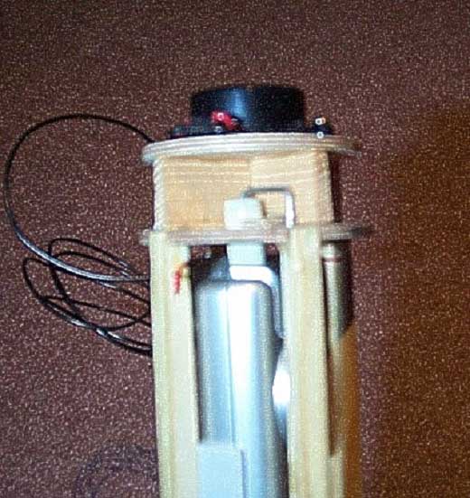
It's up to you where you mount the piezo alarm, but as you can see, I put it on top of the entire cradle on the optional 5th former. When you mount this, be careful to give it enough clearance from the servo/button rod when it moves into its upward position. If it's not far enough away, the rod will hit the underside of former 5 and as a result, you may not be able to get the button up high enough thereby preventing you from getting your camera out.
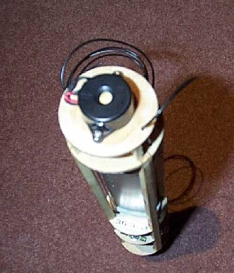
The Piezo buzzer mounted on the top of former 5.
ROCKET MODIFICATIONS
The next thing to do is modify your Arreaux to accept the ArreauxCam. This is easy. First slide the cradle with the camera on-board into the payload bay of your Arreaux. You'll notice it sticks out the top quite a bit - don't worry, this is OK. Your lens will be partially obscured by the body of your rocket. So take a measurement 10mm from the centre of the lens and mark it on your payload tube. Then take a measurement 10mm out left and right from the centre and mark these on the tube as well. Cut out the part of the lens window from your payload tube.
Before you can slide on your nose cone, you may find that it requires a little sanding to get it to fit. What I mean by this is that the inside of the plastic shoulder of your nose cone may need to be thinned a little to fit between the inside wall of your payload bay tube and former 4. I used a Dremel with a drum sanding accessory and it was very quick and easy to do. Just make sure you run the Dremel at a low speed otherwise you could melt the plastic inside the nose.
The idea is to make it a snug fit, again, to prevent any movement in flight. If you have former 5 fitted, don't worry about its size. I've made it small enough to fit up inside the nose cone.
Once you've sanded your nose cone and got it fitting snugly, slide the cone on over the exposed part of the camera and cradle.
Given that the lens window needs to be around 20mm x 20mm, work out the difference between what you've already cut out of the payload bay and the overall size of 20mm and mark it on your nose cone. Cut the hole in your nose cone and you're done.
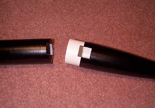
Here you can see the small piece cut out of the payload tube and the larger piece out of the nose cone. The white part of the nose is the thinned out shoulder section.
TESTING
Before your first flight, ensure you test your camera thoroughly and become familiar with its features. In fact, before you buy the camera, check that it does what you want, then go and buy it. As I said before, the pictures aren't the quality you get with a $1000 digital camera, but then what do you expect for such a low price.
Assuming you use the Dolphin Pocket Digital Camera, test the settings on your servo, like where the arm is positioned, etc, and check the controls on your transmitter so that you know when a picture has been taken. Try it out a few times to get used to it. The next step is to put it in your rocket and try taking shots again. What you're really ensuring here is that the lens window is big enough for the camera's field of view, however I have found that 20mm x 20mm is large enough.
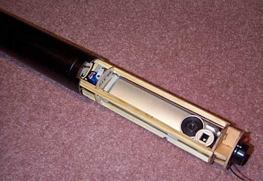
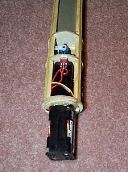
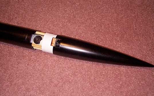
Here's the camera unit half in the payload tube.
The camera now in the payload bay ready for the nose cone.
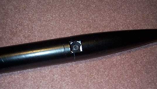
The nose cone almost slid into its final position.
The completed rocket with the camera inside.
CONCLUSIONS
At the time of writing, I haven't flown my ArreauxCam yet. I'm still trying to get a hold of a larger parachute (don't forget that - recalculate the size of your chute based on the new mass of your rocket, including batteries!).
Once I have the chute, I'll launch the ArreauxCam and see what I get back. I'll update this document as I go along with any other tips and suggestions that may come out of the flights.
Just a word of warning. By adding a camera and associated hardware, you are seriously changing the flight dynamics of your rocket. Please ensure you recalculate your CG and CP figures to ensure your rocket is stable before you go ahead and launch it.
Have Fun and Clear Skies.
If you choose to undertake this or some part of this project, you do so at your own risk. I will not be liable for any accident or injury as a result of persons building this project. This project was designed and developed by James Carter 2002. Feel free to distribute it, however please keep the document in tact as the re-posting or taking graphics from this project is expressly prohibited by international copyright (c) laws.
Submitted by James Carter