
Super Roc Rocket Gliders
Research and Development Project for NARAM 42
Bumbling Brothers Flying Circus, NAR Team 011
Robert Alway and Peter Alway
Summary
For decades, rocketeers have observed that some rockets, particularly long, slender models, will glide backwards if they fail to deploy their parachutes. Modelers usually dismiss such recoveries as “dumb luck,” but we investigated how to turn this phenomenon into a deliberate recovery system. We explain super roc rocket glide recovery with the relationships of the Barrowman center of pressure (\(B_{CP}\)), center of lateral area (\(C_{LA}\)-an approximation of the high angle-of-incidence center of pressure), and the center of gravity (\(C_G\)). We predicted that any model whose GC falls ahead of the \(B_{CP}\) and behind the \(C_{LA}\) can glide backwards. We concluded that by forcing the model to experience a high angle of attack, we could trigger the transition to a backwards glide.
We devised a model that uses a novel method of inducing this high angle of attack-an ejection port that causes a pitch maneuver–and tested the model with a variety of \(B_{CP}\)-\(C_G\)-\(C_{LA}\) relationships.
We found that an ejection port was a reliable method for transitioning to glide. We found that the range of \(B_{CP}\)-\(C_G\)-\(C_{LA}\) relationships that results in a successful rear glide recovery is narrower than expected for models that do not spin on recovery. We found that models that spin on recovery can fall sideways or glide over a larger part of the predicted range \(B_{CP}\)-\(C_G\)-\(C_{LA}\) relationships.
We have found that a small-finned, long slender model rocket with a single ejection port at the front of the tube, whose \(C_G\) is midway between the \(B_{CP}\) and \(C_{LA}\), can function predictably as a no-moving-parts rocket glider.
Introduction
On July 28, 1938, Robert H. Goddard observed a peculiar phenomenon. His model L-16, a tall, slender, fin-stabilized rocket, boosted vertically with the aid of his guidance system. At apogee, the guidance system became ineffective, and the rocket fell without guidance. Instead of descending nose first from its apogee, the rocket fell horizontally. Because of this slow, sideways descent, the parachute was able to deploy before impact, saving the rocket for another flight1. In 1969, model rocketeers observed that the tube-finned “Infinite Loop” rocket would glide backwards when it suffered a separation2. In the early 1970’s, one manufacturer, AVI, in Mineral Point, Wisconsin, produced a kit, the Linnaeus Gigantus, specifically designed to glide backwards after ejecting its nose. AVI described this kit as over 6 feet long and 2 cm in diameter and using “float recovery”3. Casual observation has shown that long, slender models are most prone to this flight-typically in the NAR Super Roc competition. One of us has even resorted to exploiting the phenomenon to fly the NAR Rocket Glider Duration event with a long, slender scale model (EAC Hyperion)4, resulting in qualified Rocket Glider flights5 in at least one NARAM. We will call conventionally configured tall, slender rockets flown with the intention of recovering in a glide under the lift of the body tube, nose cone, and fins only “super roc rocket gliders.”
Objectives
The goal of this project was to understand the reasons for the two stable modes, boost and glide, of super roc rocket gliders, to determine if the transition to glide could be made reliably, and to optimize the design of the super roc rocket gliders.
Understanding Super Roc Rocket Gliders
Our hypothesis is that two modes of stability are possible because the center of pressure of a model rocket varies with angle of attack. We have at our disposal two means of calculating center of pressure-The Barrowman equations, for near-zero angles of attack6 and the “cardboard cutout” or lateral area approach for high angles of attack7. One significant difference between these two methods is that the body tube has no effect on the low angle-of-incidence calculations while the body tube area has a siginificant effect to the high angle-of-attack calculations. The results of the two calculations can differ significantly, especially for long, small-finned models. Typically the center of lateral area (\(C_{LA}\)) is ahead of the Barrownam center of pressure (\(B_{CP}\)).
The difference between the two \(C_P\) calculations allows for one particularly interesting case. If the center of gravity is ahead of the \(B_{CP}\) but behind the \(C_{LA}\), the model will be stable in some orientations and unstable in others. At low angles of attack, the \(C_G\) is ahead of the \(C_P\), and the model will be stable moving forward, but unstable moving backwards. At high angles of atttack, the \(C_P\) is ahead of the \(C_G\) and the model will be unstable moving forward, but stable moving backwards.
Such a model will be arrow-stable at launch, but moving backwards, it will be stable at a high angle of attack and unstable at a low angle of attack. It will settle into an equilibrium angle of attack and glide.
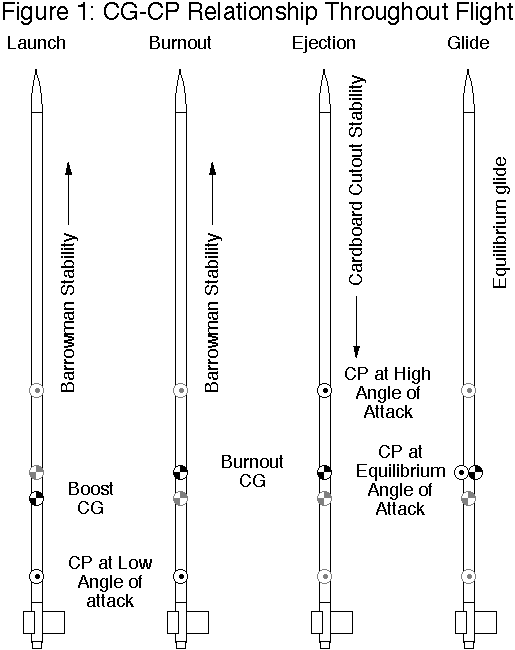
Figure 1 shows the \(C_G\)-\(C_P\) relationship of such a model at four phases of flight. 1: At launch, the relevant \(C_P\) is the Barrowman Center of Pressure, and the relevant \(C_G\) is with a full-weight engine. The model is stable moving straight forward. 2: At burnout, the \(C_G\) has moved forward, as the weight of propellant is gone. It is still stable moving straight forward. 3: At ejection or apogee, the model transitions to a high angle of attack, no longer pointing in the direction of motion. Now the \(C_{LA}\) is the functional \(C_P\), located ahead of the \(C_G\). The relative wind blows the nose back, and the model starts moving tail first. If the model points directly backward, the Barrowman \(C_P\) again becomes important, and the tail is pushed away from the direction of motion. 4: After the transition to glide, the model settles into an angle of attack where the \(C_P\) matches the \(C_G\).
Some models can be weighted to reach the condition where the \(C_G\) lies between the \(B_{CP}\) and the \(C_{LA}\), but this condition is natural for long slender model rockets with small fins-typical Super Roc contest rockets.
Transition to Glide
For a super roc rocket glider to fly successfully, it must experience a low angle of attack from launch to apogee or ejection. Adherence to the NAR safety code’s launcher and wind speed requirements has proven to be adequate to insure a low angle-of-attack boost.
Transition to glide requires that the model encounter a high angle of attack during flight, preferably near apogee. This need only be a momentary encounter. Once the model leaves the realm of low angle-of-attack arrow stability, it will tend toward the rearward equilibrium angle of attack.
There are three methods of increasing angle of attack. First, if the model is ascending perfectly vertically, the model may begin to slide backwards at the apex of its flight. This is a rare phenomenon, but we have witnessed this occasionally.
Second, ejection of the nose cone can induce a high angle of attack. This requires the ejection to drive the model into reverse, or at least to a speed comparable to any relative crosswind at the time of ejection. This method usually works (it was employed by the AVI Linnaeus Gigantus kit, and one of our previous Rocket Glide entries), at least in low winds and vertical boosts. If the model is descending rapidly at ejection, the model may maintain its low angle-of-attack arrow stability directly into the ground. One of us has deliberately used a nose-blowing scale model for qualified NAR Rocket Glider Duration competition flights.
Third, the ejection charge can be directed to increase the angle of attack. Simply by punching a hole in the body tube as far as possible from the center of gravity of the model, we can harness the ejection charge to produce a torque around the pitch axis of the model. While we are not aware of any previous use of an ejection port for a pitch maneuver with super roc rocket gliders (observation of an old Astron Sprite tumble recovery model suggests that the ejection port pitch maneuver played an important part in the tumble recovery system), it was an attractive approach for flying models with fixed geometry in our tests.
It is our intention to design super roc rocket gliders for maximum flight duration, in the hopes that they might be competitive in the Rocket Glide event, especially at high impulse levels where it is difficult to build a successful model without radio control. In our actual work, we found it challenging to map out regions where these models work; we performed limited optimization trials.
Approach
We began by writing an Excel spreadsheet that can calculate the center of pressure of a model according to the Barrowman equations and according to the lateral area method. This gave us a feel for how the two \(C_P\)’s differed. Each row of the spreadsheet represents a different model, so that we could produce plots of high- and low- angle of attack centers of pressure for a range of designs.
There are several obvious variables in performance: body length, fin size, fin shape, weight, and center of gravity. We felt that minimizing weight was an obvious asset, so we did not study that variable. We expect fin planform to be of minor importance. The significant parameters defining if a model will glide would be body aspect ratio (length), fin size, and center of gravity. For practical purposes, we experimented with a model 55 diameters long. To explore the \(C_G\)-\(C_P\) relationships, we varied fin size and center of gravity.
For test models, we settled on a no-moving-parts, three-fins-and-a-nose-cone design with ejection port for transition to glide. We varied the fin size with interchangeable tail sections. For each flight, we noted if there was a glide, and the quality of the glide. We also timed most flights.
Equipment
We used a Macintosh computer running the Excel spreadsheet (any PC running Microsoft office would do as well), a stopwatch, a conventional launch system, several Estes B6-4 engines, basic modeling supplies, and the models themselves.
Description of the Models
We built the models in three interchangeable sections. The nose cones were 4:1 ogives, 0.736” (19 mm) in diameter and 2.944” (75 mm) long, with 0.5” shoulders, produced by Balsa Machining Service. We cut off the shoulders at an angle of about 20 degrees from the original bases and sealed the bases with cyanoacrylate glue to protect them from ejection heat.
The body tubes were Totally Tubular T-20’s (equivalent to Estes BT-20), 34” (86.4 cm) long and 0.736” (19 mm) in diameter. We punched a hole about 0.25” (6 mm) in diameter about 1/2” from the upper end of the tube.
The tail sections were 2.75” (7 cm) long Red Arrow Hobbies 18 mm motor tubes with 3” (7.6 cm) long totally tubular T-20 couplers glued about 1/2” (13 mm) into the tube to double as engine blocks and tube couplers. This caused the engines to protrude 1/2” (13 mm) from the rear of the tube, allowing for taping. We glued three square fins to the tube, spaced equally around the tube, and centered along the length of the tube. The fin size varies from 3/4” (19 mm) to 3” (76 mm) inches on a side in 1/2” (12.7 mm) increments from 1” to 3”. We made fins from 1/16” balsa.
We present a model construction plan for the version with 1.5” x 1.5” fins, the “Backslider 1.5” in Figure 2.
We taped tail sections, body tubes, and nose cones together with 1/2” electrical tape on the field. We then inserted an Estes B6-4 or A8-3, secured it with tape, inserted an igniter and mounted it in an Apogee components tower launcher or on a conventional launch rod.
Data
We produced four types of data:
- We calculated Barrowman and lateral area center of pressure locations. Both sets of equations were entered into an Excel spreadsheet. We calculated and plotted results for a range of theoretical models.
- We measured center of gravity in the burnout mode by placing an expended B6-4 engine in each version of the test model. We also measured a couple launch \(C_G\)’s, but we considered this only for purposes of launch safety.
- We made qualitative notes on the stability of each test flight on ascent and descent, including transitions to and from glide. We paid particular attention to the effects of the ejection port pitch maneuver.
- We timed our flights according to NAR conventions, from launch to landing.
Results
Calculated Barrowman and Lateral Area Centers of Pressure
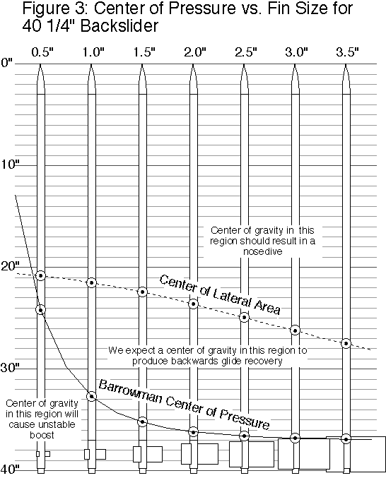
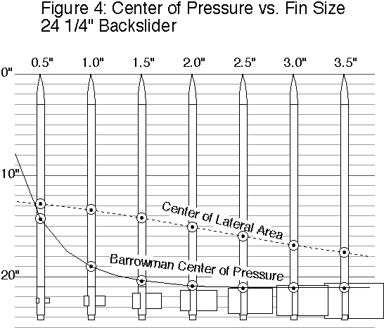
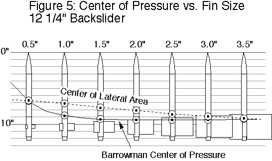
We calculated Barrowman centers of pressure (\(B_{CP}\), for low angle-of-attack) and centers of lateral area (\(C_{LA}\), for high angles of attack) for models covering a range of fin sizes and tube lengths. Figure 3 is a plot of the results for our 40 1/4”-long Backslider model with various fins. Figure 4 is a plot of the results with an 18” tube replacing the 34” tube giving a total length of 24 1/4”. Figure 5 is a plot of the results with a 6” tube giving a total length of 12 1/4”.
We predicted that we would see glide recovery when the center of gravity (\(C_G\)) fell in the region between the center of pressure (CP) curves.
Note that as the models get shorter, the envelope between the \(B_{CP}\) and \(C_{LA}\) curves shrinks, not just in absolute terms but also as a fraction of body length. In the case of the 40 1/4” model ,the distance between \(C_P\)’s is as much as 12.8”, or 32% of total length. For the 24 1/4” model, the distance between \(C_P\)’s is at most 6.2”, or 26% of the model length. For the 12 1/4” model, the distance is just 1.7” at most, or about 14% of the model length. In this case, the need for one-caliber stability at launch, and the forward shift of \(C_G\) during burn practically eliminates the chance for a backwards glide recovery.
This is consistent with the general observation that long, slender rockets are more likely to recover by a backwards glide accidentally. With both theory and experience suggesting a longer model would be more likely to perform, we concentrated our efforts on the longest model of the backslider.
Ejection Port Pitch Maneuver
Our most pleasing qualitative observation was that the ejection port pitch maneuver worked in every case. The pitch at ejection maneuver was conspicuous, and successfully triggered the transition to a high angle of attack. In many cases we could clearly see the model tumble end-over-end at ejection. This proves that a novel class of model rocket, the no-moving-parts super roc rocket glider-the Backslider-can fly successfully and reliably once the proper \(C_G\)-\(C_P\) relationship is established.
Spinning vs. Non-Spinning Recoveries
A second qualitative observation was that a model that spun rapidly around the roll axis on descent could fall horizontally or in a glide with a \(C_G\)-\(C_P\) relationship that would result in a nose dive when the model wasn’t spinning. Spin or lack of spin on recovery was not easy to control. We made no effort to induce a spin on boost, yet some flights ended up with a spin after recovering from the pitch maneuver. Because a spinning rocket was more likely to glide, we chose to examine the \(C_G\)-\(C_P\) relationships in the cases of non-spinning recoveries to define the region of reliable glide recovery.
Effects of the \(C_G\)-\(C_P\) Relationship
The table below shows calculated Barrowman center of pressure, calculated center of lateral area, measured burnout center of gravity, qualitative flight results, and times. For safety reasons, we only flew models whose \(C_G\) fell in the range likely to glide.
Flights without spin (presented graphically in figure 6)
| Fin Dimensions | \(B_{CP}\) from nose tip | \(C_{LA}\) from nose tip | Burnout \(C_G\) nose tip | Flight results |
|---|---|---|---|---|
| 0.75” x 0.75” | 29.8” | 21.0” | ~27” | Unstable |
| 1.0” x 1.0” | 32.7” | 21.5” | 27.5” | Backwards glide, 25 and 27 sec. |
| 1.5” x 1.5” | 35.2” | 22.4” | 28” | Backwards glide, 40 and 37 sec. |
| 1.5” x 1.5” | 35.2” | 22.4” | 26” | Nose dive (one of five trials w/nose weight) |
| 1.5” x 1.5” | 35.2” | 22.4” | 23.9” | Nose dive (two trials w/nose weight) |
| 2.0” x 2.0” | 36.2” | 23.6” | 28.25” | Brief glide, transition to nose dive, 11 sec. |
| 2.5” x 2.5” | 36.6” | 24.9” | 28.5” | No glide, nose dive. |
| 2.5” x 2.5” | 36.6” | 24.9” | 29” | No glide, nose dive. (w/tail weight) |
| 2.5” x 2.5” | 36.6” | 24.9” | 30” | Backwards glide (slow roll) 29 sec. (w/tail weight) |
| 3.0” x 3.0”* | 36.8” | 26.2” | ~29” | Spinning glide, nose dive when spin stopped |
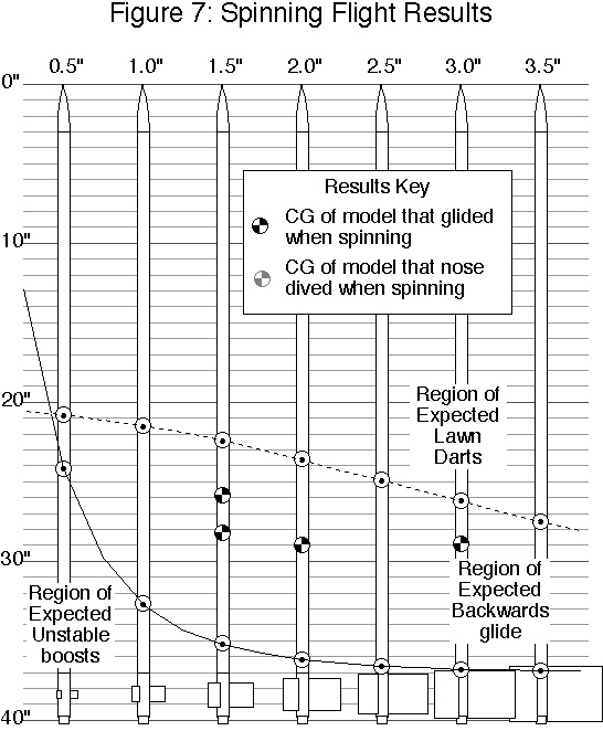
Flights with spin (presented graphically in figure 7)
| Fin Dimensions | \(B_{CP}\) from nose tip | \(C_{LA}\) from nose tip | Burnout \(C_G\) nose tip | Flight results |
|---|---|---|---|---|
| 1.5” x 1.5” | 35.2” | 22.4” | 28.2” | Spinning glide |
| 1.5” x 1.5” | 35.2” | 22.4” | 25.9” | Spinning glide (four of five trials) |
| 2.0” x 2.0” | 36.2” | 23.6” | 29 | Spinning glide |
| 3.0” x 3.0”* | 36.8” | 26.2” | ~29” | Spinning glide, nose dive when spin stopped |
A single flight of the 3”-fin model displayed both flight modes
Because out understanding of the super roc rocket glide phenomenon depends on the relationship of the burnout center of gravity, the Barrowman center of pressure, and the center of lateral area, it is useful to present this data in a way that describes this relationship. We will define the relative \(C_G\) position as the distance the \(C_G\) is in front of the \(B_{CP}\) in units of the distance between the \(B_{CP}\) and the \(C_{LA}\).
\[Relative C_G = \frac{B_{CP} - C_G}{B_{CP}-C_{LA}}\]
Where:
\(B_{CP}\) is the Barrowman center of pressure
\(C_G\) is the center of gravity
\(C_{RA}\) is the center of lateral area
If the \(C_G\) is at the \(B_{CP}\), the relative \(C_G\) is zero; if the \(C_G\) is at the \(C_{LA}\), the relative \(C_G\) is one; if the \(C_G\) is halfway between the \(B_{CP}\) and the \(C_{LA}\), the relative \(C_G\) is one half.
In the regime where the \(C_{LA}\) is forward of the \(B_{CP}\) (true for all models we studied), a negative relative \(C_G\) represents a model that is unstable at any angle of attack. A relative \(C_G\) between zero and one indicates a model that is Barrowman stable (for low angles of attack) but cardboard-cutout unstable (for large angels of attack). In this realm, we expect to see the super roc rocket glide phenomenon. A relative \(C_G\) of greater than one indicates a model that is stable at any angle of attack.
Here are the non-spinning results organized by relative \(C_G\).
| Fin Dimensions | Relative \(C_G\) | Flight results |
|---|---|---|
| 0.75” x 0.75” | 0.32 | Unstable |
| 1.0” x 1.0” | 0.46 | Backwards glide, 25 and 27 sec. |
| 1.5” x 1.5” | 0.56 | Backwards glide, 40 and 37 sec. |
| 2.5” x 2.5” | 0.56 | Backwards glide 29 sec. |
| 2.0” x 2.0” | 0.63 | Brief backwards glide, transition to nose dive, 11 sec. |
| 2.5” x 2.5” | 0.65 | Nose dive |
| 2.5” x 2.5” | 0.69 | Nose dive. |
| 1.5” x 1.5” | 0.72 | Nose dive |
| 3.0” x 3.0” | 0.74 | Nose dive after spin stopped |
| 1.5” x 1.5” | 0.88 | Nose dive |
What we see is that non-spinning models attained successful super roc rocket glider flight in only part of the predicted regime. Models only reliably glided when the relative \(C_G\) was less than about 0.6 (x0.04). If the center of gravity was located in the forward 40% of the gap between the Barrowman \(C_P\) and the center of lateral area, the models nose dived.
One possible explanation is that the center of pressure at 90x is not the center of lateral area. We suspect that a more accurate method of calculating the 90x \(C_P\) would weight the body tube and nose cone less than the fins.
Conclusions and Further Work
We have begun to assemble the design tools for designing reliable super roc rocket gliders. The super roc glide phenomenon no longer need be an accidental quirk, but a deliberate design feature. We have demonstrated a novel method for reliably pitching super roc rocket gliders into their high angle-of-attack glide modes. This could mark the beginning of an essentially new recovery system and a new class of model rocket-the zero moving parts super roc rocket glider, or what we informally call the “backslider.”
In the future, we would like to collect more data across the parameters of length, fin size, and \(C_G\) to better define the limits of the tail glide envelope, and to optimize duration.
Figures

Abbreviations
\(B_{CP}\):Barrowman center of pressure
\(C_{LA}\):Center of lateral area
\(C_G\):Center of gravity
\(C_P\):Center of pressure
Submitted by: Peter Alway
-
The Papers of Robert H. Goddard, Volume II, 1925-1937, Esther C. Goddard, Editor, McGraw-Hill, 1970, p. 1076. The rocket in question was test L-16, the movable casing rocket. It is also depicted in Rockets of the World and Retro Rockets, both by Peter Alway. ↩
-
Model Rocketry, Sept. 1969, Infinite Loop/Glider, letter to the editor by Scott Brown, p.2. ↩
-
The Encyclopedia of Model Rocketry and Space Modeling, AVI Astroport 1976 catalog, Section 1, p. 12. ↩
-
Scale Bash, Peter Alway, Saturnm Press EAC Hyperion plan for BT-50. ↩
-
United States Model Rocket Sporting Code, National Association of Rocketry, rule 37. ↩
-
Centuri technical report by James Barrowman. ↩
-
Estes technical report TR-9. ↩