Build a Launch Pad
| GROUND SUPPORT |
|
Launch Pads
Firing Consoles Clip Whips Build a Launcher Build a Launch Pad Multi-Pad Launcher Solderless Igniters Copperheads Cluster Wires |
 |
Background
The launch pad described in this write-up is a adaptation/copy of a launcher that was described on the Sunsite. This launch pad was originally developed and described by Bill Owens in the MARS (NAR Section 136) newsletter and reprinted on the Sunsite. A link to that article can be found here: Plumber’s Delight.
Construction
The pad is basic and light and consists primarily of 1 inch PVC pipe. Pickup the parts shown in Table 1 at your local hardware outlet. The part numbers listed are from Builder’s Square, if you don’t have one of them around, any Hardware or Plumbing outlet should have equivalent parts.
Table 1
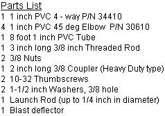
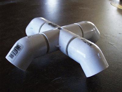
Take the 8 foot section of pipe and cut four 2 inch sections of pipe with a hacksaw. Take the remaining pipe and cut four 23 inch sections of pipe. After you are done you should have about 2.5 inches of pipe left, you’d could use this to protect the launch rod attachment from motor exhaust or provide a spacer for the rocket above the blast deflector. Take the 4 way pipe coupler and use PVC joint cleaning compound to get the joints ready to join. Do the same to the 2 inch sections you just cut. Coat the joints according to the instructions on your PVC cement compound. Insert the 2 inch sections in each of the four holes in the 4 way. Let that set for as long as the instructions on the cement label suggest. Take the four 45 degree elbows and clean up one of the ends and prepare them for gluing to the remainder of the 2 inch sections that are sticking out of the 4 way. Test fit each of the 45 degree elbows and make sure they can all be pushed completely on and make sure you can get them all lined up straight down, before applying any glue. Use a pencil to mark the best alignment on each if that will help keep them straight. Apply the PVC cement and attach the 45 degree elbow with the ends facing directly down on each of the four ends. Make sure they are as straight as you can make them and do it quickly, since the glue sets up rapidly. Take a 3/8 inch drill and drill a hole directly through the top and bottom walls of the middle of the 4 way. You should have a set up that ends up looking like Figure 1 when you are all done with this step.
FIGURE 1
The four 23 inch sections of pipe are the legs of the pad. Do not glue them into the base, as it makes
the unit more portable. If you want to
glue them on, be forewarned the footprint of this pad when assembled is quite
wide so be prepared to have lots of room in your trunk or van to take it.
The method of rod attachment differs from what is described in the previously mentioned article. An adaptation of what Bill described is shown in Figure 2. Notice 2/3rds of a turnbuckle is used and tapped a screw hole in the side to act as a lock screw to hold the rod in place. That arrangement worked fine for rockets up to C motors. When used with D’s, E’s and heavier rockets, there was quite a bit of sag at the base of the rod attachment and a lot of rod whip on launch. This lead to the following modification, Figure 3 shows the modifications to the rod attachment.
FIGURE 2
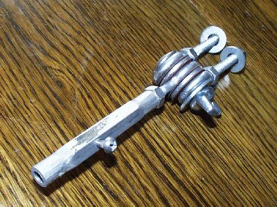
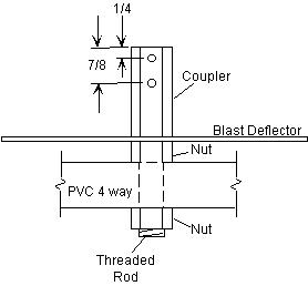
FIGURE 3
With this modification, there is no ability to adjust the angle of the pad, but the result is a more stable launcher. If you really want to angle your rod, you can find a not so level piece of ground, or buy another 8 foot section of PVC pipe and cut two sets of two legs each shorter than the first set (to make a 5 and 10 deg set up for example), or you could use a block of 2x4 propped under two of the legs.
The rod attachment uses a threaded rod, 2 nuts, 2 washers and the 2 inch coupler. Take the coupler and drill 2 holes Ľ inch and 7/8 inch from the end (Figure 3). The size of the hole is dependent upon the type of screw you use for locking the rod in place. Two 10-32 thumb screws are recommended, the drill recommended to tap a 10-32 screw is a #21 drill. Once you’ve drilled the holes tap them and test the screws to make sure they are easy to turn.
Assemble the combination as shown in the drawing in Figure 3. The blast deflector is a metal plate, placed between the coupler and the top nut. If you use a thicker material like a floor tile, you will have to cut the threaded rod longer to accommodate it. Figure 4 shows the assembled ľ and 1 inch PVC pipe units ready to launch rockets.
FIGURE 4
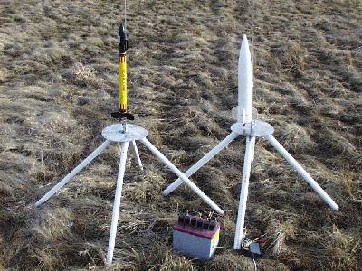
Mounting and assembly is identical for both the ľ and 1 inch version, the threaded rod on the larger pad is ˝ inch version which allows rods up to 3/8 inch.
You should be able to put the pad together in a couple of hours with normal hand tools. You may have to borrow a drill and tap. Combinations are sold in hardware stores for $4.50. It’s a handy tool to have so its not a bad investment. Without the tap you should be able to put this together for less than $10 (less if you have launch rods from previous Estes pads).
Summary
This pad has been used for rockets up to 2 lbs, equipped with G motors, and with rod sizes up to 3/8 inch. If this pad doesn’t meet your needs you may want to check out the Jan-Feb ’99 issue of NAR’s Sport Rocketry, there is a very good article on making a swivel head with a neat method of attaching the rod with a drill chuck, adapting that to a camera tripod. There is also an article on making ablative blast deflectors in the same issue.
Submitted by Eric Ohmit