Fin Flutter
| DESIGN |
| CG/CP Relation |
| Clustering Motors |
| Nose Cones |
| Rules of Thumb |
| Fin Flutter |
| Conversions |
| Transitions |
| Coning |
 |
Fin flutter is the phenomenon of a fin oscillating while in flight. In mild cases you can hear the telltale buzz or hum of the fins after the rocket is launched. In more severe cases the fins will oscillate to the point that the fin material fails and they are actually ripped off of the rocket causing a spectacular shred. Why do some rockets exhibit fin flutter and most don't? How can you predict whether a particular design will cause flutter? What does cause flutter? I decided to try and find out the answers to some of these questions recently and in my research came across a remarkable paper published by NACA in 1958 that not only examines the various types of flutter but also contains a simple algorithm for determining flutter susceptibility and determining the likely velocity at which flutter will occur. NACA performed over 100 different wind tunnel tests confirming this algorithm for various missile designs at low supersonic and subsonic airspeeds so it seems like a great place for the amateur community to start in an attempt to understand the flutter we experience. Obviously it will need to be verified for the materials, designs, and velocities that we use today.
There are at least three different types of flutter that have been examined by NACA (the precursor to NASA) rocket and missile designers: fin (wing) bending-torsion flutter, stall flutter, and pitch-bending flutter. Stall flutter occurs at high angle of attacks when the fin is near stall. Since high angles of attack and fin stall usually only occur at low velocity (near apogee) with amateur rockets it is not likely that we will experience this type of flutter. Pitch-bending flutter is reported to be less common and involves the natural frequency of oscillation of the rocket body interacting with bending of the fins. It can occur at lower speeds than bending-torsion flutter and is most likely to occur in high moment of inertia rockets with rectangular wings where the ratio of CG-to-fin-leading-edge distance to fin chord is high. I am not addressing pitch-bending flutter here, but it seems like an interesting area to investigate further. The most likely cause of fin flutter is bending-torsion flutter and is the subject here. Bending-torsion flutter occurs when two natural modes of fin oscillation interact through mutual resonance- fin bending and fin panel torsion or twisting. Figure 1 shows examples of the three types of fin flutter.
All mechanical structures have what is called a natural frequency of oscillation. The natural frequency of oscillation is distinct from vibration modes and most structures will never oscillate or even vibrate at exactly the natural frequency. Natural frequency of oscillation is one of those physical properties that you may never interact with directly but it has a great effect on the behavior of the structure. In the case of rocket fins there are actually two different natural frequencies: one associated with bending and one associated with torsion or twisting. Systems with two different types of natural frequencies may also be described as having two degrees of freedom. It is interesting that two degrees of freedom are necessary to describe fin flutter whereas the entire rocket can have its stability analyzed using just one degree of freedom (usually angle of attack). I originally thought that fin flutter would be caused by a simple resonance that made the fin flex up and down (the "bending" part of bending-torsion) but it turns out that if a fin can bend but not twist (i.e. has only one degree of freedom), or vice-versa, the air moving past the fin will damp out any oscillations. What is happening is that air moving over the not-perfectly-smooth fin puts energy into the fin. If the fin can't move, the energy becomes heat. If the fin can move it first causes the fin to bend, which stores the energy in the same way a stretched spring does. The stiffness of the fin makes the fin try and bend back. When it bends back the energy that was stored in the deflected fin now causes the fin to twist, storing the energy in the twisted fin. The pattern is now set and the bend-twist-bend-twist cycle of oscillation will continue as long as sufficient energy is being added to the system. There will be internal frictional losses in the fin that will dissipate some of the energy, but the energy contained in the moving air increases as the square of the velocity. If the rocket is accelerating during the onset of flutter then with that much energy going into the fin the oscillations will increase dramatically until the fin (possibly) fails.
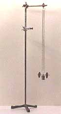
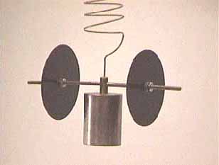
Bending-torsion flutter would be modeled by a physicist as a resonant coupled harmonic oscillator with two degrees of freedom. A well known example of this type of oscillator is the Wilberforce pendulum pictured below. It is also interesting to note that resonant coupled harmonic oscillators with two degrees of freedom can, under the right conditions, exhibit chaotic motion. Maybe that explains some of those weird flutters you've experienced!
 |
 |
To solve the flutter equations analytically is possible but it is
pretty difficult. Today aerodynamicists probably use computational fluid
dynamics or finite element analysis software to analyze these sorts of
problems. But back in the 1950's engineers would go to great lengths to
find graphical techniques or other ways to simplify problems and get
practical solutions. In 1940 NACA published a paper (reference 1) where the
authors mentioned that some of the flutter curves they had graphed could be
approximated by a simple closed-form expression or formula. In 1958, Dennis
Martin, also of NACA, seized on this discovery and extended it for use with
missiles (reference 2). He checked the formula against the flutter behavior
of over 100 different characterized missile configurations and found a
remarkable degree of correlation. Martin graphed the product of three
factors: a factor he called X (defined below), the taper ratio l, and the
ratio of atmospheric pressure to standard atmospheric pressure p/p0.
Where
A is the aspect ratio
t is the fin thickness
c is the fin root chord
Let's call Martin's three factor product the flutter index:
Where
l is the taper ratio (ratio of tip chord to root chord)
p is the air pressure
p0 is the air pressure at sea level
The flutter index is a relative index of flutter susceptibility for a given fin material which should be checked against a data set of fin designs (including fin geometry and material) and known flutter behavior. Martin did just that with his 100 data points and the plot is shown below in Figure 3.
What does all of this mean? Well the first thing to notice is that flutter susceptibility is linear with the flutter index and the smaller the flutter index the better, so if the FI doubles you are twice as well off. Doubling the fin material shear modulus also makes you twice as well off (shear modulus is described in the next section). The second thing to notice is that the thickness ratio t/c decreases the flutter index and is cubed. That means that doubling the thickness ratio makes you eight times better off. Doubling the fin root chord without changing the fin thickness makes you eight times worse off. The aspect ratio A is a bit of a mixed bag because it has a cubed term but is also divided by itself. It turns out that for the range of aspect ratios that we are concerned with (about 1.4 to 0.75), the aspect ratio will have basically a linear effect so halving the fin aspect ratio makes you only twice as well off. To finish off the discussion of the FI variables we need to consider the pressure ratio and the taper ratio. The taper ratio is a factor of one half of the change, so it has little effect. The pressure ratio p/p0 can have some moderate effect since the pressure ratio goes from 1.00 at sea level to 0.37 at 25,000 feet ASL (don't forget to factor in launch elevation). Since the pressure ratio goes down it does tend to help things out.
Summary of Relative Effects on the Flutter Index
| l | p | A | t/c | |
|---|---|---|---|---|
| Relative Effect | 0.5 | 1 | 1.04 | 1/x3 |
Figure 3 plots the flutter index against the other important factor that we need to consider, which is shear modulus. Shear modulus is a measure of the fin materials ability to resist bending and twisting, in other words it is a measure of stiffness. There are two ways to use this graph, either decide which fin material you are going to use and then determine the appropriate flutter index that you will need, or determine which material you should fabricate your fins from given the flutter index of their geometry. Martin checked each missile configuration over a range of at least 1.3 Mach. Figure 3 is not a normal plot of a dependent variable against an independent variable. Instead it is what is called a scatter plot and shows the statistical relationship of the two variables in terms of flutter susceptibility. Using Figure 3, if you draw a vertical line from the x-axis starting at the shear modulus of your fin material and a horizontal line from the y-axis starting at the flutter index number for your fin design, the intersection of those two lines is the flutter susceptibility of your rocket. If it ends up above the shaded line on the graph (in the region containing all of the black dots) your rocket will probably experience fin flutter. If the intersection lands below the shaded line your rocket is OK. For designs that end up above the shaded line you can either change your fin material (effectively moving the vertical line you drew to the right), or change your design to lower the flutter index (effectively moving the horizontal line you drew down). Of course you should also factor in some kind of safety margin.
One other formula that we can use is the formula for flutter velocity. It is not clear to me exactly what the flutter velocity actually is (onset of flutter, a figure of merit like the flutter index, or hard flutter) but the safe thing to assume is that if your rocket is near the flutter velocity you are in trouble. In any case the flutter velocity is
Where
Va is the speed of sound
GE is the shear modulus
I have made up an Excel spreadsheet that captures these equations and calculates both the flutter velocity and the flutter index. The air pressure is assumed to be sea level so that p/p0 is equal to one. I included a variety of fin styles and materials. It is interesting to note that the flutter indexes that I calculated range from about 1x10⁶ to 16.5x10⁶, which is in the upper 25% of all of the FI's that Martin examined. Similarly the shear moduli range from 4x10⁶ to 10x106 (disregarding balsa and plywood where I don't trust the numbers), which is in the upper 20% of all the materials that Martin plotted. For the materials the interpretation is simple: we have very stiff materials available to us today, perhaps stiffer than 1958. 6061-T6 aluminum has the same rating as Martin's steel does for instance. S-glass is almost as stiff as his titanium. On the other hand, the FI numbers say that our fins probably have a lower thickness ratio than in the good old days, which may not be a good thing.
Where do we go from here? All of the material presented here doesn't mean much if it can't be confirmed under actual amateur rocketry flying conditions. Maybe we don't experience bending-torsion flutter after all. The shear modulus numbers need to be checked, more materials (such as carbon fiber) added, and a data set similar to Figure 3 developed that reflects actual results with actual rockets. My dream scenario would be to check out the flutter mechanism in a wind tunnel (anyone have access?). Until then, use the flutter spreadsheet when designing your next scratch built and report your experience on ROL. I'd appreciate your feedback as well (duncan@transim.com).
![]() Fin flutter estimator (Excel spreadsheet).
Fin flutter estimator (Excel spreadsheet).
References
1. Theodorsen, Theodore Garrick, I E, Mechanism of Flutter, A Theoretical and Experimental Investigation of the Flutter Problem, NACA Report 685, 1940, pp. 46.
2. Dennis J. Martin, Summary of Flutter Experiences as a Guide to the Preliminary Design of Lifting Surfaces on Missiles, NACA TN 4197, Feb 1958, pp. 24, supersedes NACA RM L51J30.
3. Theodorsen, Theodore, General Theory of Aerodynamic Instability and the Mechanism of Flutter, NACA Report 496, 1935, pp. 23.
Submitted by Duncan McDonald